Flowserve M-series PolyChem User Manual
Page 39
USER INSTRUCTIONS PolyChem M-SERIES ENGLISH 71569218 07-11
flowserve.com
Page 39 of 60
®
6.7.3
Drive end removal - without breaking
process containment
By following the steps in section 6.7.3.1 or
6.7.3.2, the process fluid is contained and the power
end can be completely removed. This procedure does
not preclude the use of personal protective gear.
Personnel should follow their standard plant safety
practices.
The magnetic coupling will remain engaged
even after the fasteners that attach the drive end to
the wet end have been removed. This is due to the
strong radial and axial forces associated with the
magnetic coupling.
7
Do not attempt to remove the drive end
from the wet end without using the jackbolts. The
magnetic force can cause severe personal injury.
Be sure to separate the inner and
outer magnet assemblies evenly. Cocking of the two
can result in serious damage to the magnets and/or
containment shell. It is best to alternatively give each
bolt a turn to ensure proper and even separation.
6.7.3.1
Long-coupled PolyChem M-series
pumps
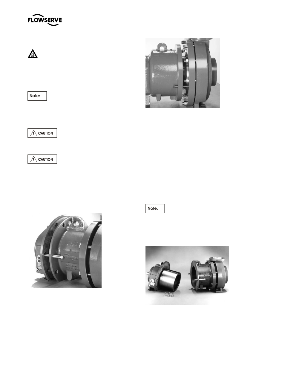
Figure 6-11: Group A and 1 pumps
Figure 6-12: Group B and 2 pumps
a)
Remove coupling guard.
b)
Remove the spacer coupling.
c)
Loosen the cap screw(s) holding the bearing
housing foot to the baseplate.
d)
To remove the power end from the wet end, on
Group A and 1 pumps remove the four (4)
bearing housing/lantern fasteners [6570.6]. On
Group B and 2 pumps remove the six (6) bearing
housing/bearing holder fasteners [6570.8].
e)
Screw the two (2) square head jackbolts [6575]
in the lantern (Group A and 1 pumps) or bearing
housing (Group B and 2 pumps) through the
threaded holes until each comes into contact
with its mating part. (see figure 6-11 and 6-12).
Continue to screw all jackbolts in evenly to
detach the wet end from the power end. (Figure
6-13 and 6-14)
It may be necessary to move the motor to
complete step e).
f)
The power end can now be moved to the repair
shop.
Figure 6-13: Group A and 1 pumps