Flowserve M-series PolyChem User Manual
Page 24
USER INSTRUCTIONS PolyChem M-SERIES ENGLISH 71569218 07-11
flowserve.com
Page 24 of 60
®
Figure 4-15: Maximum Y-Axis Loading for Shaft Deflection
SI Units
Pump Size
Suction
Discharge
Forces (N)
Moments (Nm)
Forces (N)
Moments (Nm)
Fxs
Fys
Fzs
Mxs
Mys
Mzs
Fxd
Fyd
Fzd
Mxd
Myd
Mzd
Group 1 & A
-8896
1220.4
1627.2
1695
6672
-678
2034
1695
Group 2 & B
-15568
1762.8
1762.8
4068
11120
-1627
2034
4068
US Units
Pump Size
Suction
Discharge
Forces (lbf)
Moments (
lbf∙ft)
Forces (lbf)
Moments (
lbf∙ft)
Fxs
Fys
Fzs
Mxs
Mys
Mzs
Fxd
Fyd
Fzd
Mxd
Myd
Mzd
Group 1 & A
-2000
900
1200
1250
1500
-500
1500
1250
Group 2 & B
-3500
1300
1300
3000
2500
-1200
1500
3000
Figure 4-16: Maximum Z-Axis Loading for Shaft Deflection
SI Units
Pump Size
Suction
Discharge
Forces (N)
Moments (Nm)
Forces (N)
Moments (Nm)
Fxs
Fys
Fzs
Mxs
Mys
Mzs
Fxd
Fyd
Fzd
Mxd
Myd
Mzd
Group 1 & A
4670
-5560
2034
1627
-3390
3558
8896
-13344
-2034
1356
-3390
Group 2 & B
15568
-6672
2034
1763
-4746
6227
11120
-14456
-2034
2915
-4746
US Units
Pump Size
Suction
Discharge
Forces (lbf)
Moments (
lbf∙ft)
Forces (lbf)
Moments (
lbf∙ft)
Fxs
Fys
Fzs
Mxs
Mys
Mzs
Fxd
Fyd
Fzd
Mxd
Myd
Mzd
Group 1 & A
1050
-1250
1500
1200
-2500
800
2000
-3000
-1500
1000
-2500
Group 2 & B
3500
-1500
1500
1300
-3500
1400
2500
-3250
-1500
2150
-3500
4.6.5
Pump and shaft alignment check
– Long-
coupled
After connecting the piping, rotate the pump drive
shaft clockwise (viewed from motor end) by hand
several complete revolutions to be sure there is no
binding and that all parts are free. Recheck shaft
alignment (see section 4.5). If piping caused unit to
be out of alignment, correct piping to relieve strain on
the pump.
4.6.6
Auxiliary piping
4.6.6.1
Piping connection - Oil mist lubrication
system
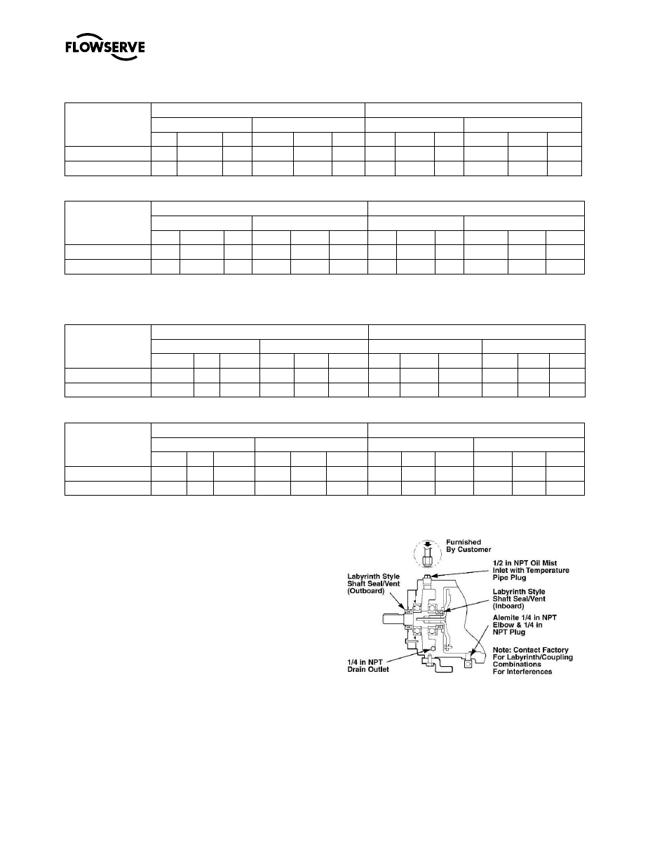
The piping connections for an oil mist lubrication
system are shown below.
Figure 4-17 Oil Mist Connections
– Labyrinth
Style Oil Seals (Standard)