5 fastener torques, 6 impeller – Flowserve M-series PolyChem User Manual
Page 35
USER INSTRUCTIONS PolyChem M-SERIES ENGLISH 71569218 07-11
flowserve.com
Page 35 of 60
®
6.5 Fastener torques
Figure 6-4: Recommended pump fastener torques - SI (US)
Item #
Comment
Size
– Lubricated torque Nm (lbf•ft)
Group 1
Group A
Group 2
Group B
6570.1
Screw
– Bearing housing foot
3/8 in.
– 20 (15)
12 mm
– 34 (25)
3/4 in.
– 127 (94)
16 mm
– 80 (59)
6570.2
Screw
– End cover/brg housing
1/4 in.
– 11 (8)
6 mm
– 11 (8)
3/8 in.
– 41 (30)
10 mm
– 41 (30)
6570.3
Screw
– Outer magnet flange
1/4 in.
– 11 (8)
1/4 in.
– 11 (8)
1/4 in.
– 11 (8)
1/4 in.
– 11 (8)
6570.4
Screw
– Adapter/motor
1/2 in.
– 11 (8)
1/2 in.
– 11 (8)
5/8"
– 20 (15)
5/8"
– 20 (15)
6570.5
Screw
– Revese rotation
5/16 in.
– 7 (5)
5/16 in.
– 7 (5)
3/8 in.
– 7 (5)
3/8 in.
– 7 (5)
6570.6
Screw
– Lantern/ Brg housing
1/2 in.
– 15 (11)
12 mm
– 15 (11)
N/A
N/A
6570.7
Screw
– Retaining ring
N/A
N/A
3/8 in.
– 34 (25)
10 mm
– 34 (25)
6570.8
Screw
– Brg housing/Brg holder
N/A
N/A
3/8 in.
– 15 (11)
10 mm
– 15 (11)
6570.9
Screw
– Hub
5/16 in.
– 24 (18)
5/16 in.
– 24 (18)
5/8"
– 20 (15)
5/8"
– 20 (15)
6580
Nut
– Casing stud
1/2 in.
– 34 (25)
1/2 in.
– 34 (25)
5/8 in.
– 61 (45)
16 mm
– 61 (45)
Note: 1) For Non-lubricated threads increase the listed value by 25%.
Figure 6-5: Recommended flange fastener torques - SI (US)
ISO Pump with PN16 Flanges
Flange Size
mm (in.)
Number
Of Bolts
Bolt Dia.
mm (in.)
Bolt Torque
Nm (
lbf•ft)
32 (1.3)
4
16 (0.63)
91 (67)
40 (1.6)
4
16 (0.63)
99 (73)
50 (2.0)
4
16 (0.63)
124 (91)
65 (2.6)
4
16 (0.63)
153 (112)
80 (3.1)
8
16 (0.63)
110 (81)
6.6 Impeller
6.6.1
Replacement
The impeller could have sharp edges,
which could cause an injury. It is very important to
wear heavy gloves.
Prior to installing the impeller [2200]
onto the shaft [2100.1] the thrust journal [3043] must
be installed.
a)
Place the impeller [2200] onto a flat surface with
the inlet facing up, refer to figure 6-6.
b)
Align the slot on the thrust journal [3043] with the
molded pin on the impeller.
c)
Press the thrust journal into the impeller until it is
seated flat.
It may be necessary to utilize an arbor press
to aid in the assembly of the thrust journal into the
impeller. If an arbor press is utilized a nonmetallic
spacer should be placed between the ram of the
press and the thrust journal. This spacer must be flat
and the entire surface area of the thrust journal
should be covered.
ANSI Pump with Class 150 Flanges
Flange Size
in. (mm)
Number
Of Bolts
Bolt Dia.
in. (mm)
Bolt Torque
Nm (
lbf•ft)
1 (25.4)
4
0.63 (16)
34 (25)
1 ½ (38.1)
4
0.63 (16)
75 (55)
2 (50.8)
4
0.63 (16)
102 (75)
3 (76.2)
4
0.63 (16)
149 (110)
4 (101.6)
8
0.63 (16)
129 (95)
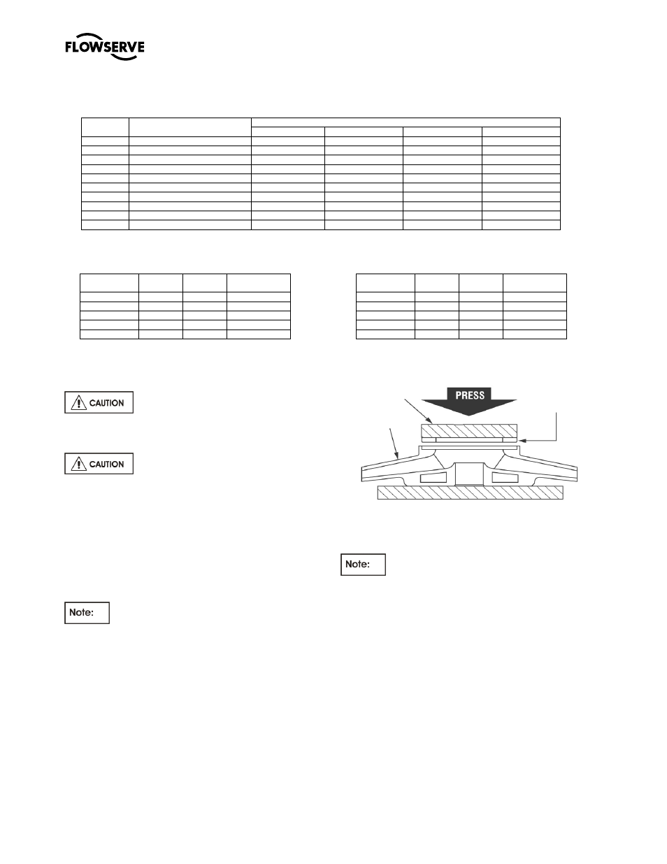
Figure 6-6
d)
Press the impeller assembly onto the silicon
carbide shaft.
It may be necessary to utilize an arbor press
to aid in the assembly of the impeller to the shaft. If
an arbor press is utilized a nonmetallic spacer should
be placed between the ram of the press and the
recently installed thrust journal. This spacer must be
flat and the entire surface area of the thrust journal
should be covered. See figure 6-7 and 6-8.
6.6.2
Trimming
If a new impeller of maximum diameter has been
acquired and needs trimming or if an existing impeller
needs trimming this is accomplished by turning
(machining). It is recommended that this trimming
operation be performed by a Flowserve
representative. However, if this cannot be
accommodated the following guidelines should be
followed.
Non metallic
spacer
Impeller
[2200]
Thrust Journal
[3043]