Flowserve M-series PolyChem User Manual
Page 20
USER INSTRUCTIONS PolyChem M-SERIES ENGLISH 71569218 07-11
flowserve.com
Page 20 of 60
®
The PolyChem product line is designed to meet the
requirements of ISO 5199 and ANSI/HI 9.6.2.
Allowable nozzle loads for ISO pumps may be
calculated using ISO 5199 or ANSI/HI 9.6.2 by
selecting a comparable pump size.
Figure 4-9: Casing Material Correction Factors
–
Material Group No. 1.0
Temp.
˚C
-29
38
93
150
Temp.
˚F
-20
100
200
300
Correction Factors
0.89
0.89
0.83
0.78
Figure 4-10: Baseplate Correction Factors
Base Type
Grouted
Bolted
Stilt
Mounted
Type A
1.0
0.7
0.65
Type B - Polybase
1.0
N/A
0.95
Type C
N/A
1.0
1.0
Type D
1.0
0.8
0.75
Type E - PIP
1.0
0.95
N/A
Polyshield - Baseplate
/ Foundation
1.0
N/A
N/A
4.6.4.1
PolyChem M-series Pumps
The following steps are based upon ANSI/HI 9.6.2.
All information necessary to complete the evaluation
is given below. For complete details please review
the standard.
a)
PolyChem M-series pumps are only
manufactured from Ductile Iron. For reference
the “Material Group No.” for this material is 1.0
b)
Find the “Casing Material Correction Factor” in
Figure 4-9 based upon the operating
temperature. Interpolation may be used to
determine the correction factor for a specific
temperature.
c)
Find the “Baseplate Correction Factor” in
Figure 4-10. The correction factor depends
upon how the baseplate is to be installed
d)
Locate the pump model being evaluated in
Figure 4-14 and multiply each load rating by the
casing correction factor. Record the adjusted
Figure 4-14 loads.
e)
Locate the pump model being evaluated in
Figures 4-15 and 4-16 and multiply each load
rating by the baseplate correction factor. Record
the adjusted Figure 4-15 and 4-16 loads.
f)
Compare the adjusted Figure 4-14 values (Step
D) to the values shown in Figure 4-13. The
lower of these two values should be used as the
adjusted Figure 4-13 values. (The HI standard
also asks that Figure 4-13 loads be reduced if
Figure 4-15 or 4-16 values are lower. Flowserve
does not follow this step.)
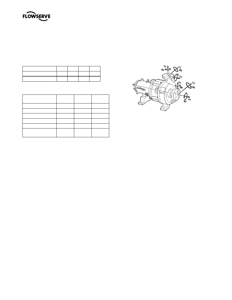
Figure 4-11: Coordinate System
g)
Calculate the applied loads at the casing flanges
according to the coordinate system found in Figure
4-11. The 12 forces and moments possible are
Fxs, Fys, Fzs, Mxs, Mys, Mzs, Fxd, Fyd, Fzd, Mxd,
Myd and Mzd. For example, Fxd designates
Force in the “x” direction on the discharge flange.
Mys designates the Moment about the “y”-axis on
the suction flange.
h)
Figure 4-12 gives the acceptance criteria
equations. For long-coupled pumps, equation sets
1 through 5 must be satisfied. For close coupled
pumps only equation sets 1 and 2 must be
satisfied.
i)
Equation set 1: Each applied load is divided by the
corresponding adjusted Figure 4-13 value. The
absolute value of each ratio must be less than or
equal to one.
j)
Equation set 2: The summation of the absolute
values of each ratio must be less than or equal to
two. The ratios are the applied load divided by the
adjusted Figure 4-14 values.
k)
Equation sets 3 and 4: These equations are
checking for coupling misalignment due to nozzle
loading in each axis. Each applied load is divided
by the corresponding adjusted load from Figure 4-
15 and 4-16. The result of each equation must be
between one and negative one.
l)
Equation set 5: This equation calculates the total
shaft movement from the results of equations 3
and 4. The result must be less than or equal to
one.