Flowserve M-series PolyChem User Manual
Page 41
USER INSTRUCTIONS PolyChem M-SERIES ENGLISH 71569218 07-11
flowserve.com
Page 41 of 60
®
On Group A and 1 pumps; if the pump
being disassembled has been pulled less casing,
upon removal of the drive end (outer magnet) the
remaining wet end components will no longer be held
together by either magnetism or bolting. Care needs
to be exercised to prevent damaging the wet end
components. On Group B and 2 pumps an eyebolt
should be installed at the 12 o’clock position on the
bearing holder [3830]. An appropriate lifting device
should be attached to the eyebolt, placing it in light
tension to support the pump.
6.7.4.1
Long-coupled PolyChem M-series
pumps
Refer to section 6.7.3.1 steps d and e.
6.7.4.2
Close-coupled PolyChem M-series
pumps
Refer to section 6.7.3.2 steps b and c.
6.7.5
Disassembly of wet end
Take care when handling the internal
bearings of the pump - journals, bushings, and shaft.
These parts are easily chipped and damaged.
6.7.5.1
Group A and 1 pumps
a)
Place the wet end assembly on the face of the
lantern. See Figure 6-19.
Figure 6-19
b)
Remove the impeller [2200].
If the impeller remains attached to the shaft
it may be necessary to utilize an arbor press to aid in
its removal as well as the removal of the inner
magnet. If an arbor press is utilized, a nonmetallic
spacer should be placed between the ram of the
press and the shaft.
c)
The assembly comprised of the impeller [2200],
shaft [2100.1], holder [3830], an inner magnet.
[0220] should be removed from the lantern.
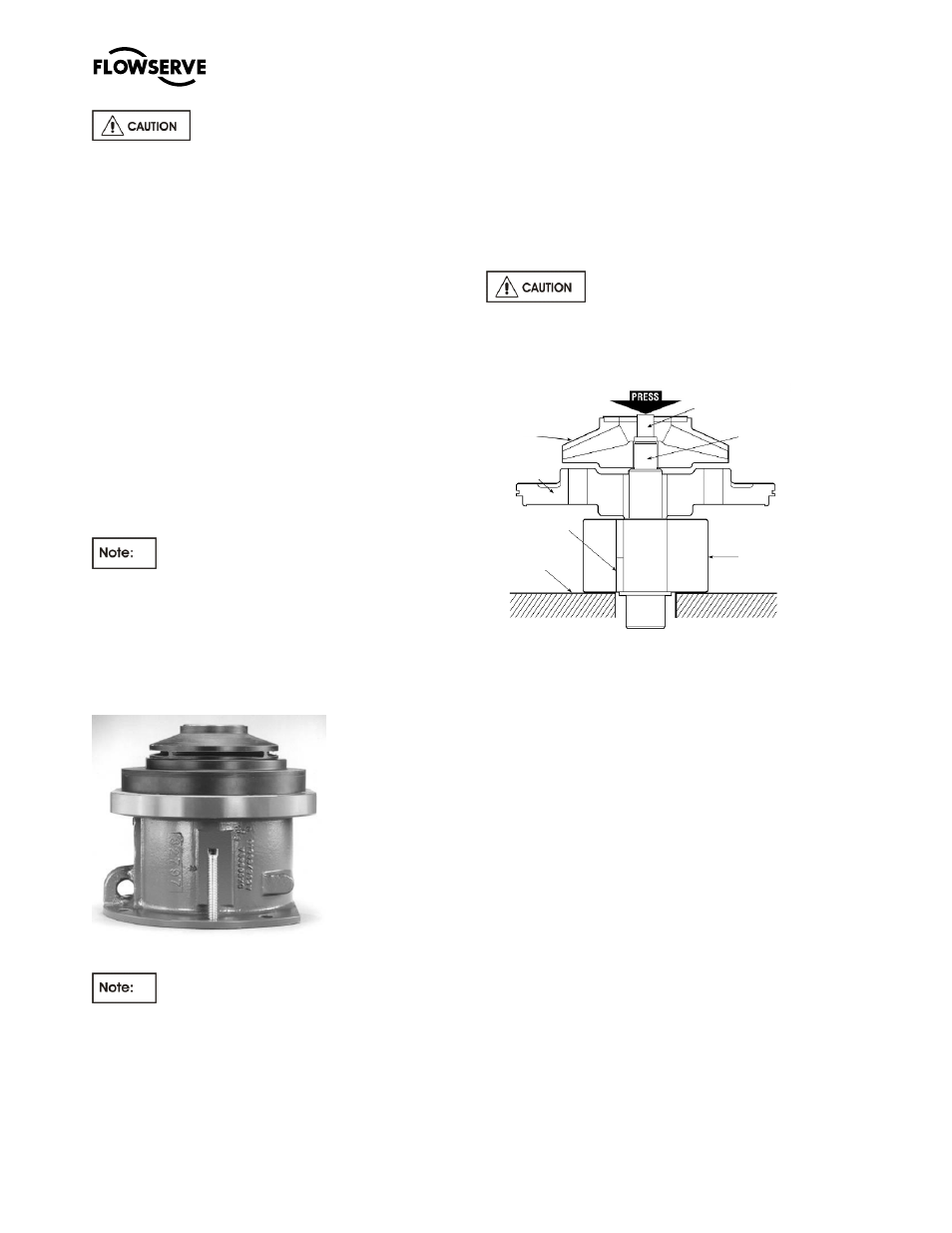
d)
This assembly should be placed on a nonmetallic
surface under an arbor press. See Figure 6-20.
e)
Using a nonmetallic spacer, press the square
end of the shaft [2100.1] until it is disengaged
from the impeller [2200].
Make sure that the shaft is free to
travel downward. Do not allow the shaft to fall as it is
being pressed free of the impeller and inner magnet.
Figure 6-20
f)
Remove the impeller [2200] and holder [3830].
g)
Continue pressing the end of the shaft [2100.1]
until it disengages from the inner magnet [0220].
h)
Remove the key [6700.2] from the shaft.
i)
Place the holder [3830] under the arbor press
and again using a nonmetallic spacer press the
inboard bushing [3300] until it becomes
disengaged.
j)
Remove the containment shell [3500] from the
lantern [1340].
6.7.5.2
Group B and 2 pumps
a)
The wet end assembly should be supported
horizontally. A tapped hole is located at the 12
o’clock position on the holder [3830] so that an
eyebolt can be engaged. An appropriate lifting
device should be attached to the eyebolt, placing
it in light tension to support the wet end. See
Figure 6-21.
Nonmetallic
Material
Key [6700.2]
Holder
[3830]
Impeller
[2200]
Inner
Magnet
[0220]
Shaft
2100.1
Nonmetallic
Spacer