Flowserve M-series PolyChem User Manual
Page 50
USER INSTRUCTIONS PolyChem M-SERIES ENGLISH 71569218 07-11
flowserve.com
Page 50 of 60
®
Install two (2) 5/8-11UNC-2B studs (180°
apart) into the hub to aid in installation of the outer
magnet assembly. These two studs will be later
removed.
d)
Mount lantern [1340] to the motor with four (4)
hex head cap screws [6570.4].
e)
Attach the outer magnet flange [0231] to the
outer magnet [0230] using socket head cap
screws [6570.3].
f)
Place the outer magnet assembly into the lantern
[1340] and use the installation studs as a guide
to support the assembly until two (2) of the
fasteners [6570.9] and corresponding lock
washers can be installed. See Figure 6-29
g)
Remove the installation studs and replace them
with the remaining two (2) fasteners [6570.9] and
lock washers.
6.9.3
Wet end assembly
The first part of these instructions pertain to both the
Group A and 1 plus Group B and 2 pump models.
In the assembly of the wet end it will be
necessary to utilize an arbor press to aid in the
assembly of the silicon carbide bearings into their
mating components. When utilizing an arbor press a
nonmetallic spacer must be placed between the ram
of the press and corresponding silicon carbide
bearing. The spacer must be flat and the entire
surface area of the component being pressed must be
covered.
a)
The casing [1100] should placed on its suction
flange. The surface on which the suction flange
is placed must be flat and care must be taken to
protect the casing liner, see Figure 6-42.
Figure 6-42
b)
Install pin [6810.2] into casing [1100] followed by
the installation of the thrust bushing [3041] taking
care to align the slot with the pin.
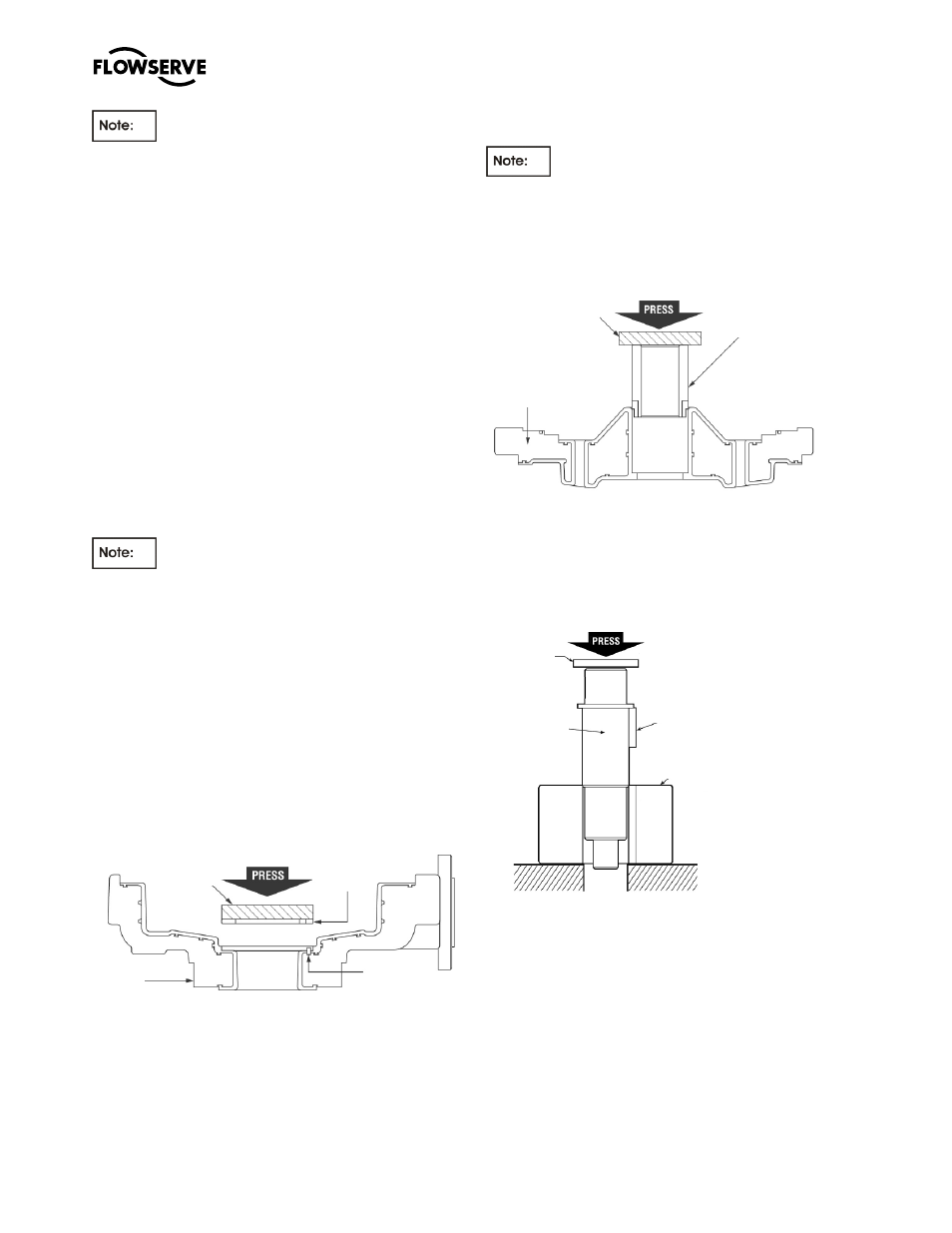
c)
Press the inboard bushing [3300] into the
bearing holder [3830], see figure 6-43.
On Group A and 1 pumps take care to align
the flat on the bushing with the flat on the bearing
holder. On Group B and 2 pumps visually align the
key slots in the bushing with the as molded keys in
the bearing holder.
Figure 6-43
d)
Install key(s) [6700.2] into the key slot(s) located
on the silicon carbide shaft [2100.1].
e)
Press the shaft [2100.1] into the inner magnet
[0220], see Figure 6-44.
Figure 6-44
6.9.3.1
Group A and 1
a)
Place the lantern [1340] on a work bench with
the flange incorporating the lifting lug towards the
work bench, see Figure 6-45.
b)
Install the containment shell [3500] into the
lantern followed by the inner magnet/shaft
assembly and then the bearing holder/bushing.
Non metallic
spacer
Casing
[1100]
Pin
[6810.2]
Thrust bushing
[3041]
Non metallic
spacer
Bushing
[3300]
Bearing
holder
[3830]
Non metallic
spacer
Key
[6700.2]
Inner Magnet
[818/220]
Shaft
[2100.1]