Flowserve M-series PolyChem User Manual
Page 49
USER INSTRUCTIONS PolyChem M-SERIES ENGLISH 71569218 07-11
flowserve.com
Page 49 of 60
®
Install the outboard seal in the bore of the bearing
cover with the single expulsion port positioned at the
6 o’clock position.
Magnetic seals
Follow the installation instructions provided by the
manufacturer.
6.9.1.3
Bearing cover/shaft/power end assembly
a)
Clean the interior surfaces of the bearing
housing and cover with a non-flammable solvent
cleaner.
b)
Place the wavy washer [4260] in the bearing
housing [3200]. Slide the shaft [2100.2] with
anti-friction bearings installed into the bearing
housing [3200] (Figure 6-24).
The axial location of the shaft/anti-friction
bearing assembly is accomplished after the bearing
cap is installed and the wavy washer is compressed.
The compression results in preloading the anti-friction
bearings which is essential for proper bearing
operation.
c)
Install a new O-ring [4610.9] into the bearing
cover [3260] utilizing a small amount of grease to
hold it in place.
d)
Place the bearing cover [3260] onto the shaft
[2100.2] slide it towards the bearing housing
[3200] and then secure it with the three (3)
fasteners [6570.3].
e)
Reinstall the following items onto the bearing
housing; oil level tag (Figure 6-25 and 6-26) and
combination Trico oiler/site gage [3855],
vent/breather [6569.2] and drain plug [6569.1].
f)
Attach the outer magnet flange [0231] to the
outer magnet [0230] using socket head cap
screws [6570.3].
g)
Install the Flowserve impeller wrench and key
onto the input shaft of the pump. The wrench
handle should be touching the workbench
towards the right as you are facing the suction
flange of the pump.
h)
Screw the outer magnet flange assembly onto
the drive shaft.
i)
Using gloves, raise the impeller wrench until it is
parallel with the work bench (but still facing
towards the right as you face the suction flange
of the pump), spin the outer magnet rapidly in a
clockwise direction to impact the impeller
wrench on the work bench. After several sharp
raps, the outer magnet assembly should be tight.
The threads are right hand.
j)
Insert the flat head cap screw [6570.8] into the
center of the outer magnet flange and tighten.
Again the threads are right hand tight.
k)
The assembly of the power end is complete.
6.9.2
Power end assembly
– Close Coupled
6.9.2.1
Group A and 1
a)
Attach a new motor gasket [4590.2] and lantern
gasket [4590.1] to the motor flange [6540].
b)
Mount the motor flange [6540] to the motor with
four (4) socket head cap screws [6570.4] see
Figure 6-17.
c)
Attach the outer magnet flange [0231] to the
outer magnet [0230] using socket head cap
screws [6570.3].
d)
Attach the hub [7200] to the outer magnet
assembly using the four (4) fasteners [6570.9]
supplied with the hub, see Figure 6-28.
e)
Place the key supplied with the motor in the
motor keyway and mount the outer magnet
assembly onto the motor shaft. Engage the
assembly onto the motor shaft till the face of the
outer magnet flange [6540] contacts the end of
the shaft. This ensures the proper axial location
of the magnet poles.
f)
Tighten the set screw in the hub to secure the
outer magnet assembly to the motor shaft.
6.9.2.2
Group B and 2
a)
Attach a new motor gasket [4590] to the lantern
[1340].
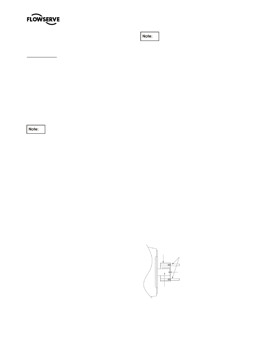
b)
Place the key supplied with the motor in the
motor keyway and mount the hub [7200] to the
shaft. The end of the hub must be aligned with
end of the shaft, see figure 6-41.
Figure 6-41
c)
Tighten the set crews in the hub to secure it to
the motor shaft, figure 6-29.
Hub [7200]
Installation
Studs
Hub and end of
motor shaft must
be aligned
Motor
shaft