Flowserve M-series PolyChem User Manual
Page 19
USER INSTRUCTIONS PolyChem M-SERIES ENGLISH 71569218 07-11
flowserve.com
Page 19 of 60
®
short length of flexible piping. The pump should not
have to support the weight of the pipe or compensate
for misalignment. It should be possible to install suction
and discharge bolts through mating flanges without
pulling or prying either of the flanges. All piping must be
tight. Pumps may air-bind if air is allowed to leak into
the piping. If the pump flange(s) have tapped holes,
select flange fasteners with thread engagement at least
equal to the fastener diameter but that do not bottom
out in the tapped holes before the joint is tight.
The following is the recommended procedure for
attaching piping to the PolyChem M-series pump (see
section 6.5 for torque values)
Check the surface of both flanges (pump/pipe) to
ensure they are clean, flat, and without defects
Lubricate the fasteners
Hand tighten all of the fasteners in a crisscross
pattern
The fasteners should be torqued in increments
–
based a crisscross pattern
o The first increment should be at 75%
of the full torque
o The second increment should be at the
full torque
o Verify that the torque value of the 1
st
fastener is still at the full torque value
Retorque all fasteners after 24 hours or after the first
thermal cycle
Retorque all fasteners at least annually
4.6.2
Suction piping
To avoid NPSH and suction problems, suction piping
must be at least as large as the pump suction
connection. Never use pipe or fittings on the suction
that are smaller in diameter than the pump suction size.
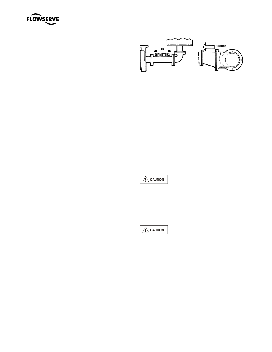
Figure 4-7 illustrates the ideal piping configuration with a
minimum of 10 pipe diameters between the source and
the pump suction. In most cases, horizontal reducers
should be eccentric and mounted with the flat side up as
shown in Figure 4-8 with a maximum of one pipe size
reduction. Never mount eccentric reducers with the flat
side down. Horizontally mounted concentric reducers
should not be used if there is any possibility of entrained
air in the process fluid. Vertically mounted concentric
reducers are acceptable. In applications where the fluid
is completely de-aerated and free of any vapor or
suspended solids, concentric reducers are preferable to
eccentric reducers.
Figure 4-7 Figure 4-8
Avoid the use of throttling valves and strainers in the
suction line. Start up strainers must be removed shortly
before start up. When the pump is installed below the
source of supply, a valve should be installed in the
suction line to isolate the pump and permit pump
inspection and maintenance. However, never place a
valve directly on the suction nozzle of the pump.
Refer to the Durco Pump Engineering Manual and
the Centrifugal Pump IOM Section of the Hydraulic
Institute Standards for additional recommendations
on suction piping. (See section 10.)
Refer to section 3.4 for performance and operating
limits.
4.6.3
Discharge piping
Install a valve in the discharge line. This valve is
required for regulating flow and/or to isolate the pump
for inspection and maintenance.
When fluid velocity in the pipe is high,
for example, 3 m/s (10 ft/sec) or higher, a rapidly
closing discharge valve can cause a damaging
pressure surge. A dampening arrangement should
be provided in the piping.
4.6.4
ALLOWABLE NOZZLE LOADS
Introduction
Never use the pump as a support for piping.
Maximum Forces and moments allowed on pump
flanges vary based on the pump size. When these
forces and moments are minimized, there is a
corresponding reduction in misalignment, hot
bearings, worn couplings, vibration and possible
failure of the pump casing. The following points
should be strictly followed:
Prevent excessive external pipe load
Never draw piping into place by applying force to
pump flange connections
Do not mount expansion joints so that their force,
due to internal pressure, acts on the pipe flange