Fluke Biomedical IDA-5 User Manual
Page 16
Advertising
IDA-5
Users Manual
6
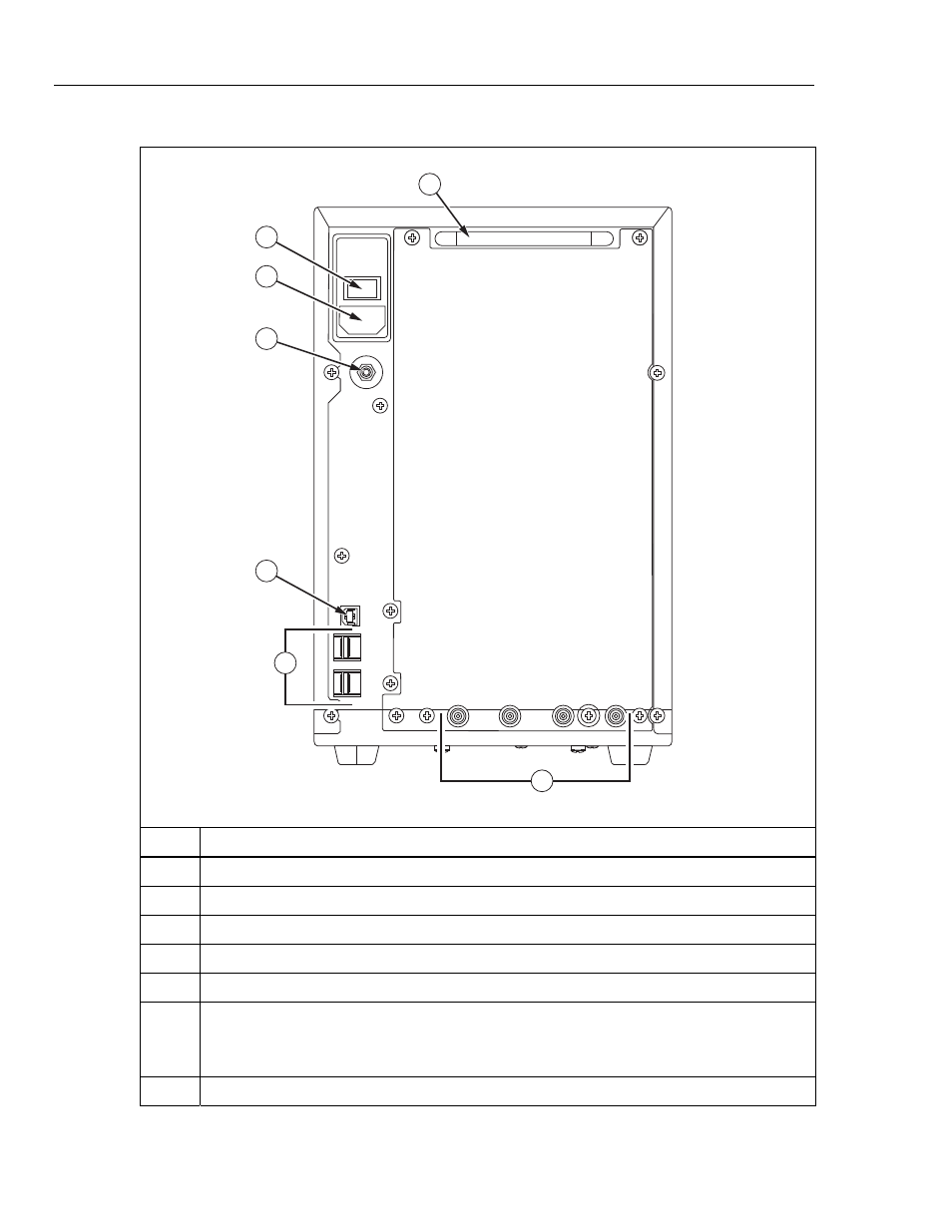
Table 3. Rear-Panel Controls and Connections
2
1
3
4
5
6
7
gir02.eps
Item Description
Handle
Power switch
Power inlet
Equipotential post
USB “B” connector – Computer connection.
USB “A” connectors – Connect a maximum of four accessories such as:
Keyboard
Printer
Bar-Code
reader
Fluid outlets – One per measurement channel. Channel 1 at right and channel 4 at left.
Advertising
This manual is related to the following products: