Jumper, Function, Remarks – Fluke Biomedical 942A-200L-M4 User Manual
Page 32
942A-200L-M4 & 942A-200L-M5 UDR
Operator Manual
2-18
Buffer Amplifier
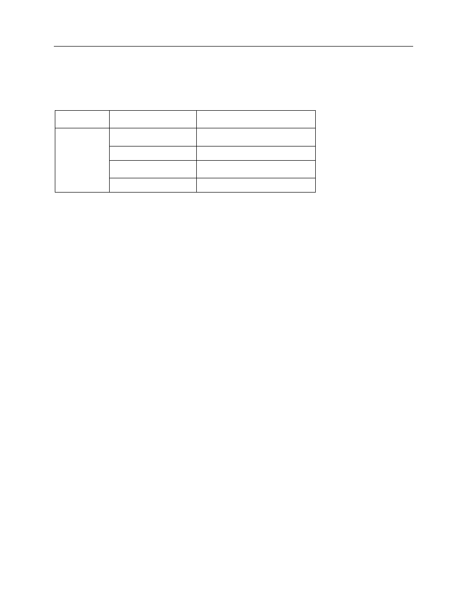
The detector input is connected to J6. The input impedance is 50 ohms to match the signal cable and the
detector’s output impedance. Jumpers JP4 and JP5 are used to select the proper pulse polarity as
shown below.
Jumper
Function
Remarks
JP4 1-2
Pulse Polarity (Input)
For negative input (factory set),
Scintillation Detectors
JP4 2-3
Pulse Polarity (Input)
For positive input, GM Detectors
JP5 1-2
Pulse Polarity (Shield)
For negative input (factory set),
Scintillation Detectors
JP5 2-3
Pulse Polarity (Shield)
For positive input, GM Detectors
The detector input signal (with appropriate polarity jumpers installed) is applied to unity gain buffer
amplifier U90. VR8 is used to fine adjust for unity gain. Regardless of input signal polarity, U90-6 outputs
positive going pulses. VR9 is a zero offset adjust for U90. The buffer amplifier output is provided to the
J7 connector (for use by analyzer option circuitry) as well as the high and low discriminators. TP-1 is
available as a test point for this pulse.
Discriminators
The low level discriminator is comprised of comparator U91 device 2 and associated circuitry. VR11 is
used to set the trip threshold. The adjustment range is 50 mV to 1 volt, which can be measured at the
low discriminator test jack. As the positive pulse, applied to the input, passes through the trip threshold,
the output (U91-6) is forced low. When the pulse returns through the trip threshold, the output U91-6
returns high and is ready to accept another input pulse. Pulses below the trip threshold do not trigger the
output.
The high discriminator is comprised of comparator U91 device 1 and associated circuitry. VR10 is used
to set the trip point. The adjustment range is 3.5 to 7.5 volts, which can be measured at the high
discriminator test jack. As the positive pulse, applied to the input, passes through the trip threshold, the
output (U91 device 1) is forced low. When the pulse returns through the trip threshold, the output (U91
device 1) returns high and is ready to accept another input pulse. Pulses below the trip threshold do not
trigger the output.
The normal factory setting are: Low Disc.: 0.500 Vdc
High Disc.: 7.000 Vdc
Figure 2-5 shows signal “A” below both discriminators, signal “B” between discriminators, and signal “C”
above discriminators.