Signal, Internal connection, Connector – Fluke Biomedical 942A-200L-M4 User Manual
Page 67
Appendix
Connector Designations
A
A-3
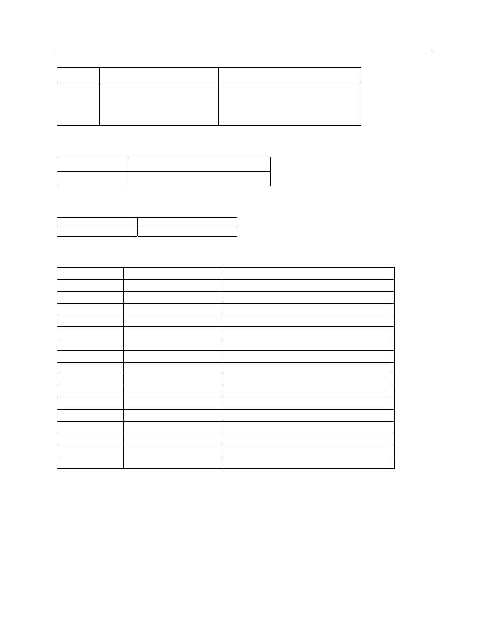
Table A-3. Connector P3 - Power Input
Pin
Signal
Internal Connection
1
120 VAC – LINE
Line Fuse (F2)
2
120 VAC – Neutral
Power Supply 120 VAC (N)
3 Safety
Ground
Chassis
Table A-4. Connector P4 - Detector High Voltage
Connector
Signal
P4 High
Voltage
Table A-5. Connector P5 - Detector Signal Input
Connector
Signal
P5
Input Signal
Table A-6. Connector P6 - Auxiliary I/O
Pin Signal
Internal
Connection
1
4-20 mA output
Main circuit board J5-8
2
GND
Main circuit board J5-7
3
4-20 mA output
Main circuit board J5-6
4
GND
Main circuit board J5-5
5
0-10 mV analog output
Analog Option W3-c
6
GND
Main circuit board J5-9
7
0-5V
Main circuit board J5-4; Analog Option J4-6
8
GND
Main circuit board J5-3; Analog Option J4-2
17
Not Provided
Analog input option board J2-1
18
Not Provided
Analog input option board J2-2
19
Not Provided
Analog input option board J2-3
20
Not Provided
Analog input option board J2-4
21
Not Provided
Analog input option board J2-5
22
Not Provided
Analog input option board J2-6
23
Not Provided
Analog input option board J2-7
24
Not Provided
Analog input option board J2-8