Fluke Biomedical 942A-200L-M4 User Manual
Page 37
Theory of Operation
Relay Circuit Board (942-200-55, Appendix B)
2
2-23
2.4 Relay Circuit Board (942-100-70, Appendix B)
The relay circuit board contains five independently controlled mechanical relays. Each relay provides two
Form C sets of contacts with the exception of the check source relay which provides a single Form C set
of contacts. Interconnection is from J2 on the relay board to J2 on the main circuit board. The control
signals (active low) and + 15 volts common are provided. The relays typically perform the following
functions:
K1: Optional Rate-of-Rise/ Auxiliary Function
K2: Check Source
K3: Fail
K4: Warn
K5: Alarm
The relay contacts are provided to the user via rear panel connector P1, with the exception of the check
source via detector connector P2. See specifications for contact ratings. Varistors (V1-V16) provide
transient protection across the contacts.
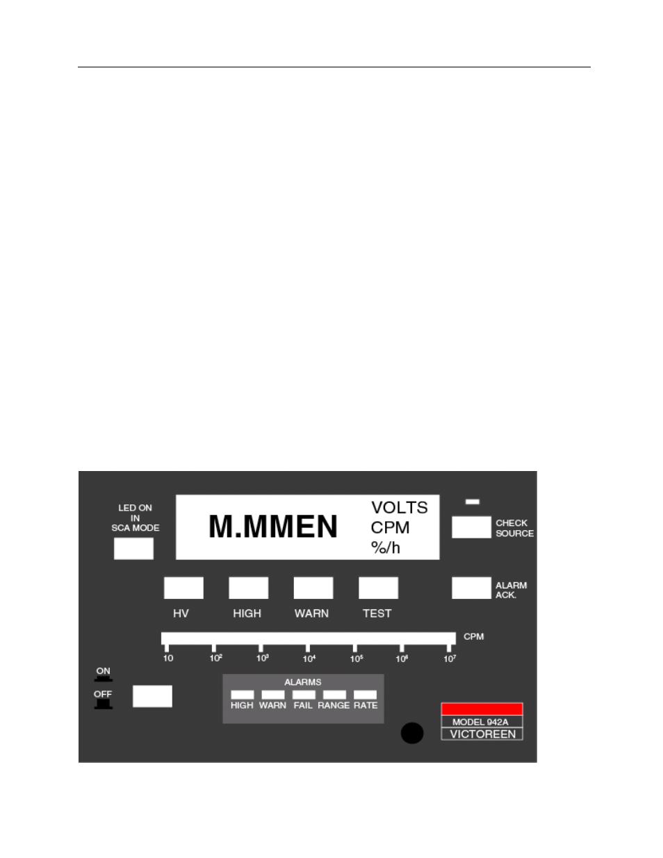
2.5 Front Panel Circuit Board (942-100-15, Appendix B)
The front panel circuit board consists of the 7 segment display, backlights, status indicators, switches,
and bargraph assembly. The front panel interfaces to the main circuit board via interconnecting row 100,
200, and 300. The main power switch also mounts to the front panel circuit board. Refer to Figure 2-7 for
a view of the front panel.
Circuit Description (Front Panel Circuit Board)
The 7 segment displays are controlled by the display controller as described in ”Display Control.” The
bargraph is controlled by the circuitry described in “Bargraph (Write Only).” The status indicators are
described in “Status Indicators (Write Only).” Switches are described in “Switch Inputs.”
Figure 2-7. Front Panel, Model 942A-200L-M4