Function, 14 analog output – Fluke Biomedical 942A-200L-M4 User Manual
Page 58
942A-200L-M4 & 942A-200L-M5 UDR
Operator Manual
3-18
E0004 is also displayed if the analog output set points are invalid. This would occur when the Full Scale
value is set below or equal to the Analog Low Scale value, or the Analog Low Scale value is set above or
equal to the Analog Full Scale value. A minimum of 1-decade separation between the Analog Full and
Low Scale set points is required.
E0004 will also be displayed if the Full Scale or Low scale set point values are not set to an even power
of 10 (e.g. 1.00EX, where X= an integer between –9 and +9).
The appearance of either code may indicate that the setpoint memory has not been initialized.
Code E0007 identifies the set point function select switch is in a position where no set point has been
defined. To clear the E0007 press the ENTER push button and move the function select switch to an
active point position.
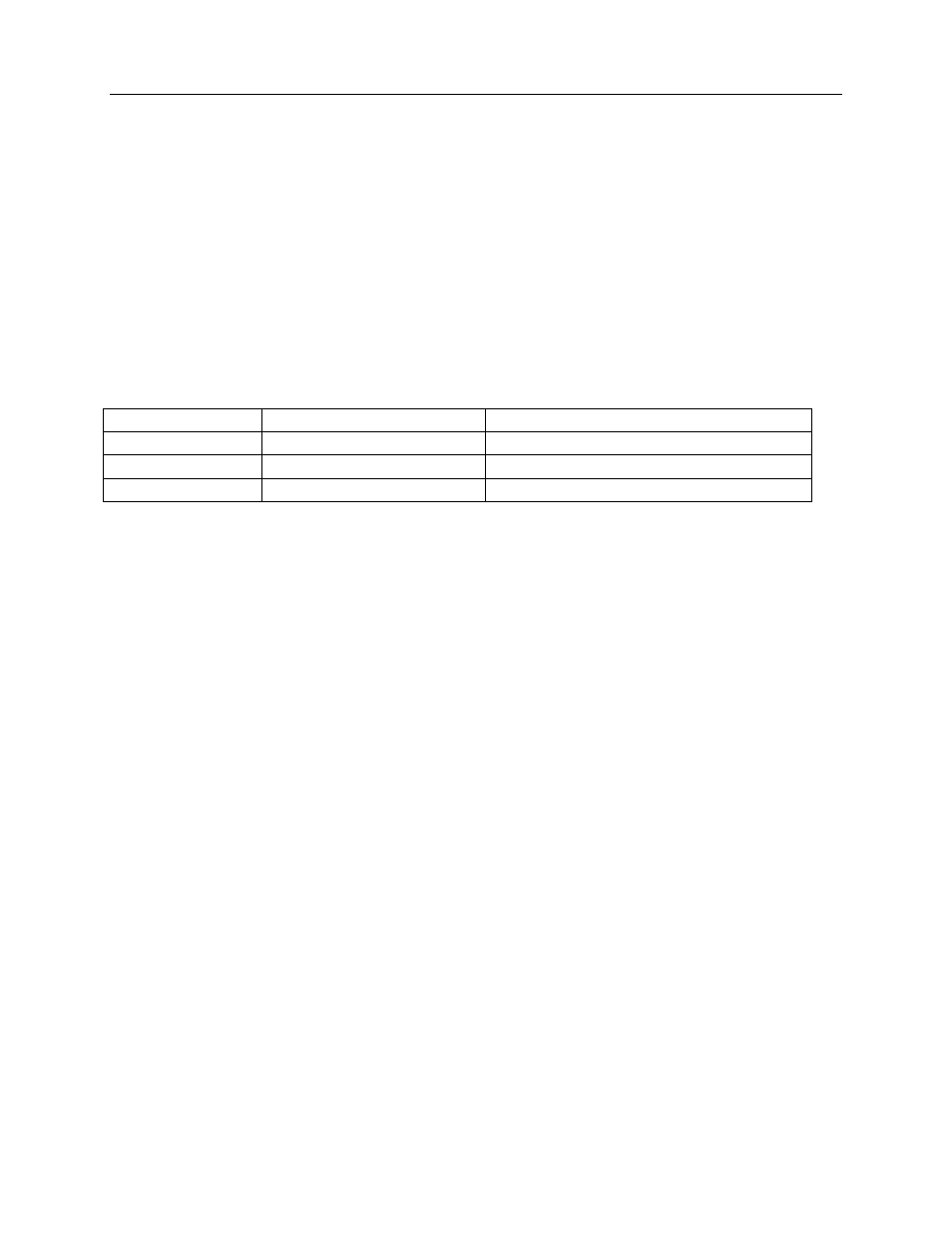
Table 3-4. Model 942A-200L-M4 and 942A-200L-M5 Error Codes
Error Codes
Function Reference
Section
E0001
Negative display data
Re-initialize to reset
E0004
Invalid setpoint value (s)
Automatically resets after 4 seconds
E0007
Invalid set point selected
Press the ENTER button to reset
3.14 Analog Output
The analog outputs are a logarithmic function of the current UDR reading. The outputs are scaled by the
Full Scale Value and Low Scale Value, positions 3 and 7 respectively of the FUNCTION switch. An 8-bit
DAC is used to convert the displayed dose rate to a 4-20 mA, 0-10 Vdc or optional analog output value
output on connector P6 (on the rear panel). Output current or voltage is calculated using the following
equations (shown below):
P
=
log (R/LSV)/ [log (FSV) -log (LSV)]
and
V
=
P (VMax -VMin) + VMin or
I = P (IMax -IMin) + IMin
where:
P
= Percent of scale, expressed in a decimal number
R
= Current reading
LSV
= Low Scale Value
FSV
= Full Scale Value
V
= Voltage output
I
= Current output
VMax = Maximum voltage available (usually 10Vdc)
IMax = Maximum current available (usually 20 mA)
VMin = Minimum voltage available (usually 0 Vdc)
IMin
= Minimum current available (usually 4 mA)
If the current reading (R) is greater than the full-scale value (FSV) the output is limited to the MAX value
(typically 10 Vdc or 20 mA).