Switch position, 10 udr function switch/function, 11 parameter entry – Fluke Biomedical 942A-200L-M4 User Manual
Page 55
Operation
UDR Function Switch/Function
3
3-15
3.10 UDR Function Switch/Function
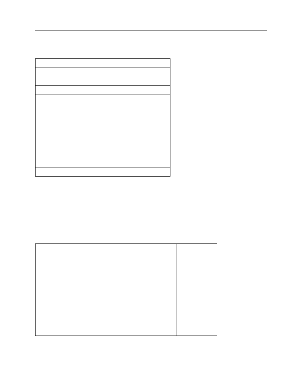
Table 3-2 UDR Function Switch RDS1 Positions/Function (Refer to drawing 942-200-10, Appendix B,
for Function Switch Location)
Switch Position
Function
0
Selects HIGH Alarm Setpoint
1
Selects WARN Alarm Setpoint
2
Selects Resolving Time (Tau) Limit
3
Selects Analog Full Scale Limit
4 Selects
Overrange
Limit
5 Selects
Calibration
Constant
6 Background
Subtract
7
Selects Analog Low Scale
8 Selects
Calibrate
Mode
9 Not
Used
A-E Not
Used
F Unit
I.D.
3.11 Parameter Entry
Parameter entry is accomplished using a sixteen position rotary switch labeled FUNCTION and three
momentary pushbutton switches labeled ENTER, VALUE, and DIGIT. These switches are located on the
right side of the main circuit board and are accessible by partially removing unit from its mounting case.
The FUNCTION switch is used to select the parameter to be entered. Table 3-3 defines the switch
positions and a description of each parameter can be found in the following paragraphs.
Table 3-3. Function Switch Entry Parameters
Switch Position
Setpoint
Units
Factory Setting
0
High Alarm Limit
CPM
1.00E5
1
Warn Alarm Limit
CPM
1.00E3
2
Resolving Time (Tau)
Minutes/count
0.00E0
3
Full Scale Value
CPM
1.00E7
4 Overrange
CPM
1.00E7
5 Conversion
Constant
-
1.00E0
6 Background
Subtract CPM
0.00E0
7
Low Scale Value
CPM
1.00E1
8
Calibration Mode
Seconds
6.0E1
9
Not Used
N/A
E0007
A thru E
Not Used
N/A
E0007
F Unit
I.D.
N/A
1.00E0