Test pulse width, Detector type, Dc value at r94 – Fluke Biomedical 942A-200L-M4 User Manual
Page 63: Equivalent cpm, Jumper j7
Maintenance, Calibration and Troubleshooting
Calibration
4
4-3
Signal Input DC Offset and Gain Adjustment (Factory Set)
1. Disconnect the detector signal input.
2. Set the DVM to the 1-volt range.
3. Connect the positive lead of the DMV to TP-1 (labeled PULSE on the edge of the printed circuit
board) and the negative lead to the ground test jack.
4. Short the signal input connector on the rear panel (P5)
5. Adjust VR9 for a DVM reading of 0.000 volts.
6. Disconnect the DVM and connect an oscilloscope (to channel 2) positive lead to TP-1 and the
negative lead to the ground test jack.
7. Disconnect the short on the signal connector, on the rear panel (P5).
8. Connect a signal generator to P5.
9. Connect an oscilloscope to channel 1 to monitor the signal generator output.
10. Adjust the signal generator output to obtain a 1 microsecond negative going pulse, with a -1 volt
amplitude at a 1 kHz repetition rate.
11. Adjust VR8 to obtain unity gain. A -1 volt input should produce a +1 volt output pulse.
High and Low Discriminator Adjustments
Refer to the appropriate detector calibration procedure.
Anti-Jam Threshold Adjustment (Factory Set)
This adjustment is dependent on the type of detector used. Potentiometer VR12 is used to adjust the DC
level measured at R94. Table 4-2 shows the DC adjustment values necessary for each detector type
unless otherwise specified.
Table 4-2. Anti-Jam Threshold Adjustment
Test Pulse Width
Detector Type
DC Value at R94
Equivalent CPM
Jumper J7
1 microsecond
(250 kHz)
943 Series
Gamma Family
1.170 V
1.5 x 10
7
1 to 2
800 ns
(250 kHz)
943 Series
Beta Family
0.950 V
1.5 x 10
7
1 to 2
10 microsecond
(50 kHz square wave)
843-251 Series
GM Probe Family
0.900 V
3 x 10
6
2 to 3
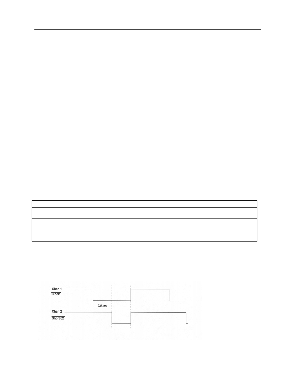
Write Cycle Clock Adjustment (Factory Set)
1. Connect the channel 1 oscilloscope (x10 probe) to U19-2 (clock).
2. Connect the channel 2 oscilloscope (x10 probe) to U19-12 (short 02).
3. Adjust VR13 to obtain: