Connecting the remote control jacks, Connecting other equipment, Advanced connections – Marantz SR5004 User Manual
Page 24
NAMES AND
FUNCTIONS
22
BASIC
CONNECTIONS
BASIC
OPERA
TION
ADV
ANCED
CONNECTIONS
SETUP
ADV
ANCED
OPERA
TION
TROUBLESHOOTING
OTHERS
ADV
ANCED
CONNECTIONS
ENGLISH
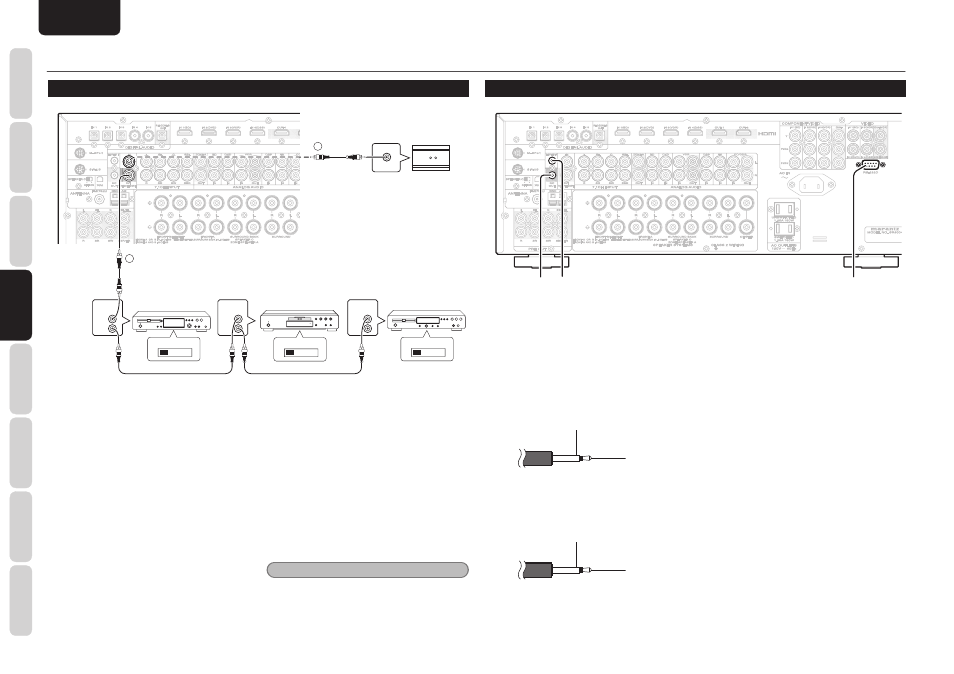
ADVANCED CONNECTIONS
CONNECTING THE REMOTE CONTROL JACKS
IN
IN
OUT
OUT
REMOTE CONT.
REMOTE CONT.
REMOTE
CONTROL
REMOTE
CONTROL
REMOTE
CONTROL
IN
OUT
IN
OUT
IN
OUT
EXTERNAL INTERNAL
EXTERNAL INTERNAL
EXTERNAL INTERNAL
1
RC OUT
2
DVD player
CD recorder
CD player
IR Receiver
q
You can control other Marantz products through this
unit with the remote controller by connecting the
REMOTE CONTROL terminals on each unit.
The signal transmitted from the remote controller
is received by the remote sensor on this unit. Then
the signal is sent to the connected device through
this terminal. Therefore you need to aim the remote
control only at the unit. Also, if a Marantz power
amplifi er (some models excluded) is connected to
one of these terminals, the power amplifi er’s, power
switch is synchronized with this unit’s power switch.
Set the REMOTE CONTROL SWITCH on the back
of other units (not the SR6004/SR5004) to “EXT.”
(EXTERNAL) to use this feature.
w
Whenever external infrared sensors or similar devices
are connected to REMOTE IN of the unit, be sure to
always disable operation of the infrared sensor on the
unit by using the following procedure.
1.
Hold down the SURROUND MODE button
and the MENU button on the front panel at
the same time for fi ve seconds.
2.
The setting “IR=ENABLE” is shown on the
FL DISPLAY.
3.
Press
the
CURSOR buttons (
1, 2) to change
this to “IR=DISABLE”.
4.
Press
the
ENTER button. Once this setting
is made, the infrared sensor on the unit is
disabled.
Note
• Be sure to set to “IR=ENABLE” when external
infrared sensors or similar devices are not
connected. Otherwise, the unit will be unable to
receive remote control commands.
5.
To restore the original setting, perform
steps
1 to 4 to set to “IR=ENABLE”.
CONNECTING OTHER EQUIPMENT
FLASHER IN
FLASHER IN
DC
DC
OUT
OUT
RS-232C
RS-232C
d
s
a
a RS-232C
Connect an external control device or other device for
servicing. (Use a straight cable for the connection.)
s DC OUT (DC TRIGGER)
External devices can be controlled from the unit
by connecting them to the DC OUT terminal (12 V
44mA max).
GND
+12V
d FLASHER IN
This unit can be controlled by connecting a control
box or other control device to this unit.
GND
Signal