Olson Technology MUSCLE-EM55X User Manual
Page 15
Advertising
OTOT-EM55X/XL Optical Transmitter Rev. x1
www.olsontech.com
14
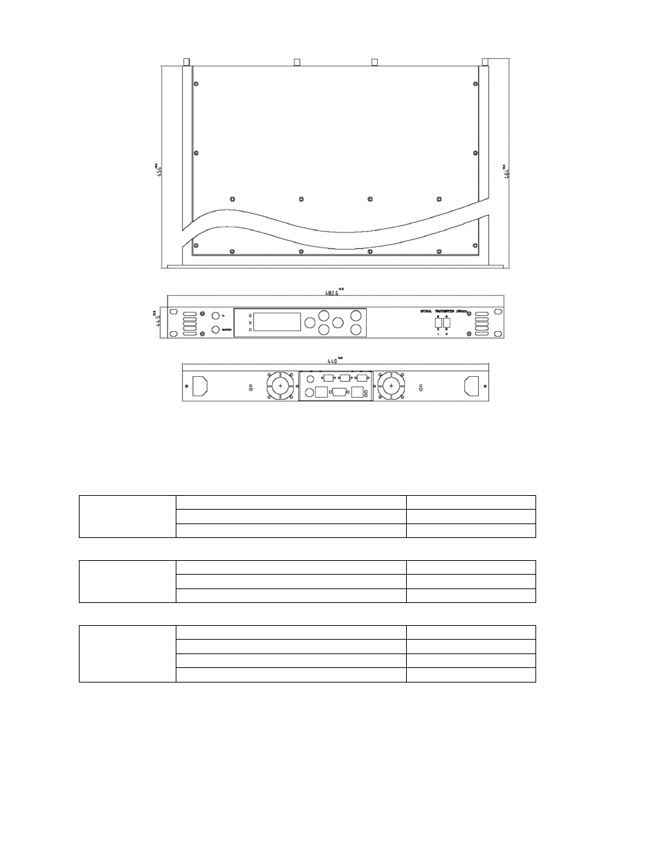
Figure 5 — Unit Line Drawing
Displays and Alarms
The tables below show the conditions that trigger the LED’s on the front panel. The “Modul” LED summarizes the
condition of the transmitter. The “IN” and “Out” LED’s provide detailed information of the input and output status of
the transmitter.
Standard Operation
LED green
Non-Urgent Alarm (warning)
LED yellow
Modul LED
Urgent Alarm
LED red
Nominal Input Power
LED green
Input Power Out of Nominal Operation
LED yellow
IN LED
Loss of Input Power
LED red
Nominal Output Power
LED green
Lack of Output Power
LED yellow
Loss of Output Power
LED red
OUT LED
Standby – Operation
LED dark
Advertising
This manual is related to the following products: