Olson Technology MUSCLE-EM55X User Manual
Page 23
OTOT-EM55X/XL Optical Transmitter Rev. x1
www.olsontech.com
22
Mode: AGC-on, CW Unmodulated Carriers (factory setting)
Most tests (CNR / CSO / CTB) are performed with unmodulated carriers using a Matrix generator or a CATV headend,
with the modulation switched off. These tests should be performed in the “AGC-on, CW unmodulated carrier” mode.
The OMI
totrms
should be set to the factory setting (0 dBr). This mode is also the recommended mode for standard op-
eration with real picture modulation. Be aware, that for AM-VSB TV channels the carrier levels with modulation de-
creases by about 4dB, however, depending on the picture content. This decrease in input level has to be compensated
by the AGC for optimum signal transmission.
For proper operation, an appropriate input signal has to be connected to the OTOT-EM55X. At least 2 RF channels
with a channel spacing of 24MHz (software adjustable) are required to obtain a stable performance.
The nominal channel load (factory settings) for the OTOT-EM55X family however is given in the table below:
Model
yy
# AM TV channels
(0 dBr)
# FM channels
(at -4dBr)
# QAM64
channels
(-10dBr)
TV channel level
[dBµV]
Total RMS OMI
[%]
Total
Level
[dBm]
D84 84
0
0
80
19.4 -9.5
N77 77
0
0
80
18.6 -9.9
The OTOT-EM55X has a built-in RF power meter function, which monitors the total level at the input of the transmit-
ter as given in the right most column of the table beyond. This level depends on the number of unmodulated and
modulated AM-TV, FM-radio and QAM channels.
The input monitor controls the INPUT LED. As long as the input level is within the AGC range of the transmitter to
obtain the specified total RMS modulation index, the input LED is lightening in green colour.
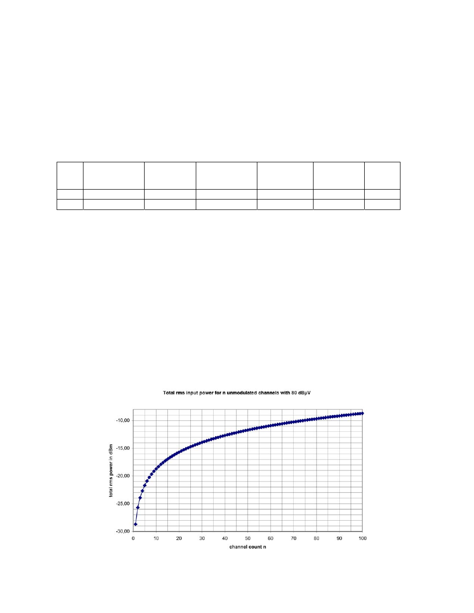
If the number of channels to be transmitted is different from the specified number of channels the total input power
level can be calculated using the following expression:
P
intot
/dBm = 10 log (n) + U
in
/dBµV –108.7
Where:
• P
intot
is the total RMS input power level
• n is the number of channels
• U
in
is the input voltage per channel (nominal 80dBµV) for unmodulated carriers.
If the input level voltage of all channels is 80dBµV, the diagram below can be used to determine the total input power
level.
Figure 18 — Total RMS Input Power for N Unmodulated Channels with 80dBµV