Operating the otot-em55x – Olson Technology MUSCLE-EM55X User Manual
Page 22
OTOT-EM55X/XL Optical Transmitter Rev. x1
www.olsontech.com
21
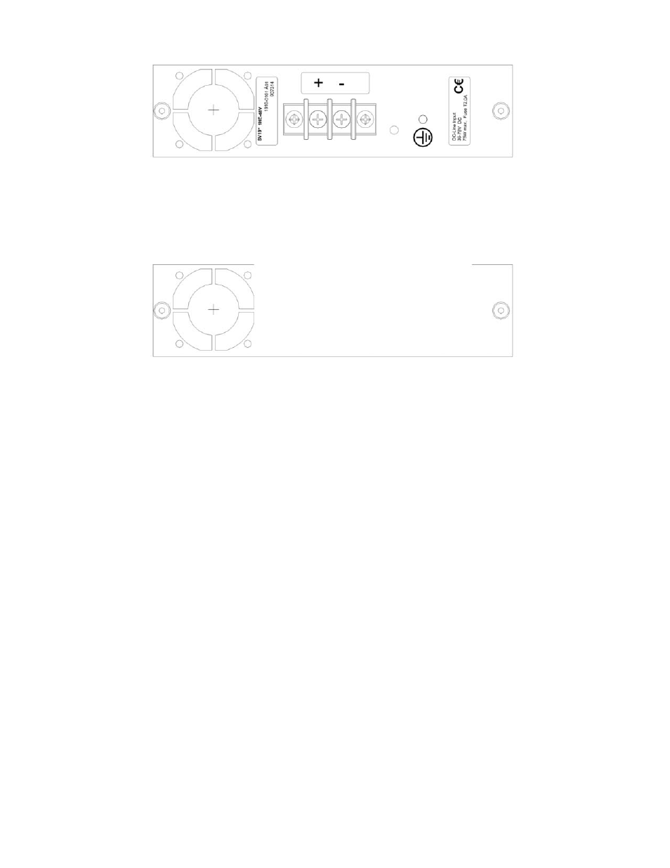
Figure 16 — 48 Volts DC Power Supply Drawing
Fan-only Module
For applications, where only one power supply is required, Olson Technology offers a fan-only module sshown in
Figure 17. The fan-only module can be exchanged during operation (hot plug-in technology) without harming the
equipment or having any impact on the operation of the transmitter in case of a properly working power supply.
Figure 17 — Fan-Only Module Drawing
Operating the OTOT-EM55X
Power-Up Sequence
• Be sure that the OTOT-EM55X is going to be put into operation under the specified environmental conditions.
Avoid temperature shocks after transportation of the OTOT-EM55X and allow sufficient time to accommodate
the environmental conditions at the operating site.
• If not already completed, install the appropriate power supply with fan modules, respectively fan-only modules.
• Connect the OTOT-EM55X to one or two (in case of redundant power supplies) appropriate power supply lines.
If only one power supply cable (instead of two) is connected to an OTOT-EM55X equipped with redundant
power supplies, an alarm will be generated and shown with a yellow brightening MODUL LED.
• After startup (with appropriate power line connections), the MODUL LED lights green and the LCD illumina-
tion is on. Then the LCD illumination switches off and all front side LED’s light yellow for a short time in order
to enable an LED test. Afterwards all LED’s should be green and the microcontroller should begin to test the
laser and optical modulator. During this test, which takes about 70 seconds, the optical output power on both
outputs varies between zero power and about twice the nominal power (P
outnom
+ 3dB). Afterwards with no
RF-input signal applied, the output power may vary about ±1 dB on both outputs, since the CSO control
loop, which fixes the bias point of the modulator and consequently the output power, only works precisely
with a RF input signal applied.
• After this procedure the LED’s should monitor the status of the transmitter.
Setting appropriate operating conditions for the OTOT-EM55XL/XL
Applying an Appropriate RF Input Signal
With an appropriate input signal, the transmitter starts to search for the optimum bias point of the LiNbO
3
modulator.
After about 30 seconds, the optical output levels of both outputs are stabilized. Connect a fiber optic cable with an ap-
propriate, cleaned connector to one of the optical outputs in order to feed a HFC network. Keep in mind that the
OTOT-EM55X is, according to IEC EN 60825, a laser class 1M product which requires adequate safety precautions to
avoid hazards to people working with the OTOT-EM55X.
There are 3 AGC on/off RF modes that can be selected in order to operate the OTOT-EM55X.