Olson Technology MUSCLE-EM55X User Manual
Page 39
OTOT-EM55X/XL Optical Transmitter Rev. x1
www.olsontech.com
38
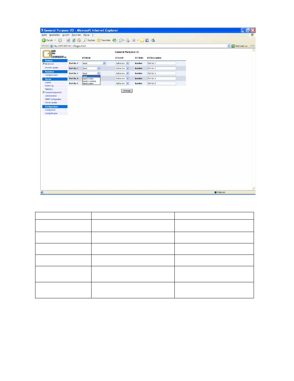
Figure 30 — Available Modes of Operation for the Input-only Ports
The available modes of operation for the I/O ports are given in the table below:
Port mode
Description
Application (examples)
Input
Input signal
(default = factory stetting)
Somebody entered the headend
(available on ports 1 … 5)
Input is notify
Input signal creates a notify message (exclama-
tion mark) in status display
Somebody entered the headend
(available on ports 1 … 5)
Input is warning
Input signal creates a warning message (orange
flag) in status display
Temperature in room is too high
(available on ports 1… 5)
Input is alarm
Input signal creates an alarm message (red
flag) in status display
Headend failure
(available on ports 1-5)
Output on any alarm
Output will become active with any alarm.
Alarm limits for the OTOT-EM55XL can be set
in limit menus of OTOT-EM55XL
(available for port 1)
Output on any warning
Output will become active with any warning.
Warning limits can be set in limit menus of
OTOT-EM55XL
(available for port 1)
All ports can be set to be either active low or active high. A description of the I/O port function can be added to each
port optionally
Examples of I/O port status information
An OTOT-EM55XL polls also an EDFA via the RS-485 interface.
Please note, that the I/O port #0 is directly related to the transmitter unit whereas all other I/O ports (#1-5) are related
to the NEC.