Olson Technology MUSCLE-EM55X User Manual
Page 24
OTOT-EM55X/XL Optical Transmitter Rev. x1
www.olsontech.com
23
Example 1: The OTOT-EM55XL-PALD84 is specified for 84 TV channels. The nominal input level voltage per carrier
is 80dBµV, which corresponds to an input level power of -28.7dBm for one unmodulated channel only. For 84 un-
modulated channels the total input level will be –9.5dBm.
The specified, guaranteed AGC range of the OTOT-EM55X is +3 / -6dB. The recommended standard input level range
is therefore 77 to 86dBµV per channel or -12.5 to-3.5dBm total input power. In reality, however, the non-guaranteed
AGC range, will be significantly larger, typically about +5 / -8dB allowing total input level powers of about –14.5 to
–1.5dBm to be accepted without input power alarms.
Example 2: If the transmitter is only operated with 60 unmodulated channels, all with 80dBµV, the total input power
level can be determined to be –11dBm, therefore –1.5dB below the specified total RMS input power. This level is still
well within the AGC range of the transmitter. If the modulation of the carriers is switched on, however, the power of
each modulated carrier drops by about 4dB. In this case the total power also drops by 4dB to -15dBm.
This –15dBm is even below the extended AGC range and an input level alarm will be generated. In order to get back
into the AGC range, an increase of the input level to at least –9.5dBm (unmodulated carriers) is recommended, which
corresponds to 81.5dBµV in this example. It would even be beneficial to compensate also for the drop of the total in-
put power due to the AM modulation, which in most cases is about 4dB. In this case an input level of 85.5dBµV is re-
quested per carrier.
If the input power is lower or higher than required, the input LED lights yellow and a warning is generated. If the in-
put power is missing, the input LED lights red and an alarm is generated.
The AGC always tries to maintain the requested optical modulation index. The modulation index determines the
amount of bit errors, which come up due to overmodulation (clipping) of the transmitter.
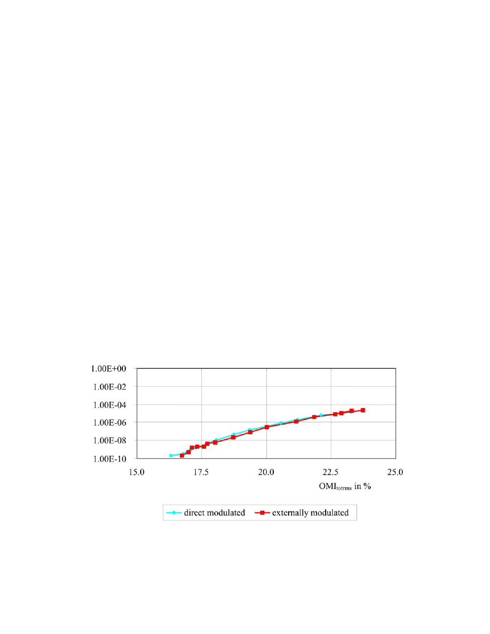
The subsequent diagram shows the relationship between OMI
totrms
and the bit error rate (BER) measured for QAM64
transmission. Obviously, OMI
totrms
should be below about 20% in order to obtain BERs better than 10
-6
.
The BER also depends on the mix of AM, FM and QAM channels. If the QAM load is very small compared to the AM
and FM load the OMI
totrms
might be chosen about 1 dB higher while still obtaining the BER as given in the diagram
below.
Figure 19 — BER of Signals
The OTOT-EM55X is typically factory adjusted to achieve a BER of 10
-9
with most frequency plans using the built in
AGC function. Experienced users are free to change the factory preadjusted OMI
totrms
by up to +3 / -3dB in steps of
0.2dB and/or to use the OTOT-EM55X in non-AGC mode. This gives the flexibility to optimize the total system CNR
or CSO/CTB performance.