Parts list, Ordering information, General description introduction – Olson Technology MUSCLE-EM55X User Manual
Page 7
OTOT-EM55X/XL Optical Transmitter Rev. x1
www.olsontech.com
6
Parts List
This document contains the description for the following units:
Transmitter Unit
Modular, internally modulated 1550nm optical trans-
mitter.
I/O Ports
Optional
Power Supply and Fan Module
power supply + fan module 100 V
AC
... 240 V
AC
power supply + fan module ±36 V
DC
... ±60 V
DC
fan-only module
Optical Interface
SC-APC optical connector, 8° angle (default)
FC/APC optical connector, JDS-standard (default)
Ordering Information
Base Model
Version
Freq. Plan
Optical Conn.
RF Conn.
Power Supply
OTOT-EM55 X
N77 = NTSC
PAL84 = PAL
2 = SC/APC
3 = FC/APC
F = Front of Unit
R = Rear of Unit
230 = 1x (100-240V
AC
)
48 = 1x (±36-±72V
DC
)
OTOT-EM55 XL
N77 = NTSC
PAL84 = PAL
2 = SC/APC
3 = FC/APC
F = Front of Unit
R = Rear of Unit
230/230 = 2x (100-240V
AC
)
48/48 = 2x (±36-±72V
DC
)
230/48 = Mixed 230V
AC
/48V
DC
General Description
Introduction
The optical transmitter OTOT-EM55X represents a family of externally modulated 1550nm DFB laser transmitters.
These products have been developed to fulfil the requirements of modern Hybrid Fibre Coax networks for the trans-
mission of CATV, cable phone and cable data signals. Two base versions are available
The Model OTOT-EM55X version is intended for applications with a fiber length <50km and features a SBS threshold
of 16.5dBm, a narrow line width laser (0.65MHz), dual +6dBm optical outputs and a RS485 interface for EMS (ele-
ment management systems).
The Model OTOT-EM55XL should be used in applications with a fiber length exceeding 50km. This version offers a
SBS threshold which can be adjusted between 13 and 19dBm, a very narrow line width laser (0.3MHz), dual +6.0dBm
optical outputs, ITU-grid compatible wavelength which can be adjusted by ±100GHz, a 10/100 Ethernet Webserver
and SNMP interface for EMS/NMS (element/network management systems). Network server and transmitter firmware
updates are available for downloading via the Internet, future-proofing the unit.
Both transmitters offer two different standard frequency plans. Specifications for other frequency plans are available
on request.
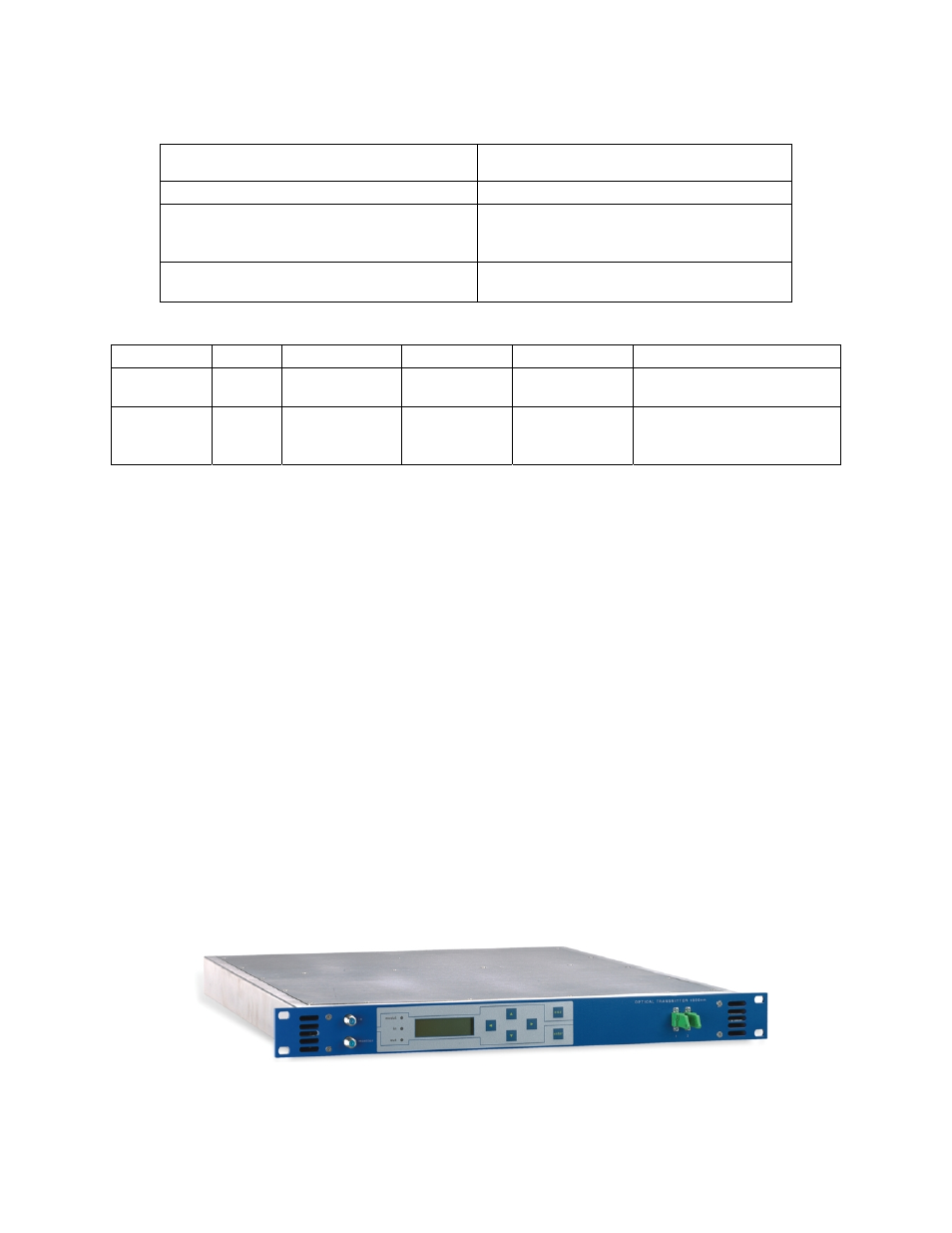
The optical transmitter comes in a 6ne unit high 19” housing, Figure 1 shows the view of an OTOT-EM55X with RF
in socket, RF-monitor socket and optical connectors on the front panel. Optionally these connectors can be located on
the rear panel.
Figure 1 — Model OTOT-EM55X Front View
A Liquid Crystal Display (LCD) provides information about actual settings and properties. Six push buttons are used
to enter data locally. The background light of the LCD switches on automatically, when a push button is pressed.