Olson Technology MUSCLE-EM55X User Manual
Page 20
OTOT-EM55X/XL Optical Transmitter Rev. x1
www.olsontech.com
19
Note: The local setup process can only be executed when the device starts up. After startup this interface has no func-
tion yet, but in the future will be used for modem connections.
Device bus interface: RS485-master (XL)
The RS485 interface can be used to connect more devices to be managed by the Ethernet NMS server interface in-
stalled in the optical transmitter. The OTOT-EM55XL in this case works as a network element controller
(RS485-master), which polls all equipment that is connected to the RS485 port.
Device bus interface: RS485-slave (X)
The RS485-slave interfaces can be used to manage the OTOT-EM55X, which reads data and changes the settings. Ad-
ditionally, on a SUB-D9 male connector beside the RJ-45 a RS485 to RS232 level converter is included. Using this
port, software on any WINDOWS based PC can communicate with the OTOT-EM55X by using the COM1 or COM2
ports.
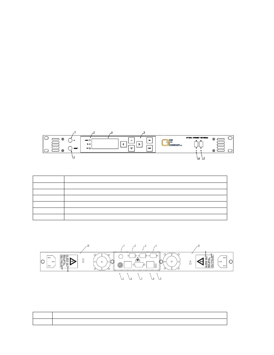
Front Panel
Figure 13 shows an example of the front panel view of the OTOT-EM55X. The RF-input and the optical connectors
are optionally available on the rear panel. The handles can be omitted on request.
Figure 13 — Model OTOT-EM55X Front Panel Drawing
Item #
Function
1
RF-input (optionally available on rear side)
2
RF-monitor output
3
Status LED’s
4
Liquid Crystal Display
5
Push button field for local set-up of transmitter
6, 7
Optical connectors (optionally available on rear side)
Rear Panel
The rear panel provides several field replaceable units.
Figure 14 — Model OTOT-EM55X Rear Panel Drawing
Item #
Function
1
RF-input (optional located on front panel)