Olson Technology MUSCLE-EM55X User Manual
Page 17
OTOT-EM55X/XL Optical Transmitter Rev. x1
www.olsontech.com
16
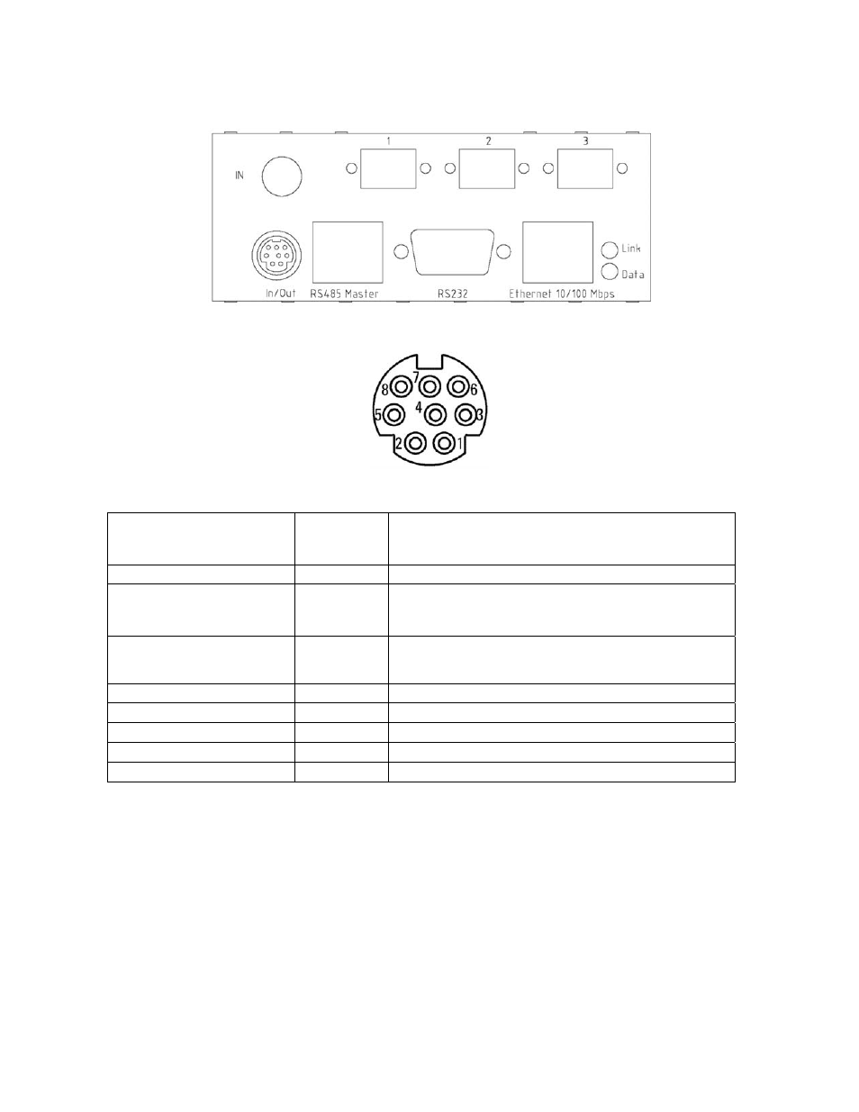
The OTOT-EM55XL uses an 8 pin Mini-DIN connector for external Input/Output handling. The connector is located
on the backside of the device near to the NMS RS485 Master connector.
Figure 8 — Model OTOT-EM55XL Rear Panel Connectors
Figure 9 shows the view on the 8 port mini-DIN connector.
Figure 9 — 8-Port Mini DIN Connector
The mini-DIN connector pins are used as described in the following table.
Function in TOT-EM55X
Pin Number
of mini-DIN
connector
Comments
GND
2
Ground
+5.1V
DC
(+/- 5%)
(voltage under no-load condition)
1
Max. 80mA, protected by a serial
PTC (< 50Ohms) in NEC hardware release 2.1
Fuse (< 6Ohms) from NEC hardware release 2.2
Input / Output No. 0
(from hardware release 2.0 and
software release 2.0)
5
Used for redundancy switching feature (input port) or as alarm output
port.
Input / Output No.1
7
Either Input or Output, configurable by Software;
Input only No.2
3
Input mode configurable by Software
Input only No.3
8
Input mode configurable by Software
Input only No.4
4
Input mode configurable by Software
Input only No.5
6
Input mode configurable by Software
Notes:
• On pin 1, there is a 5.1V
DC
(±5 %) supply voltage available for feeding an external interface box, which could
contain optocouplers or relays, external sensors etc.; the current sinked from this port should not exceed 80mA.
• I/O #0 is directly related to the transmitter. If the port is used as an output, alarms related to the transmitter can
be accessed on this output. If the port is used as an input it enables easy redundancy switching between two re-
dundant OTOT-EM55XL.
• I/O #1 to 5 are directly related to the NEC. The output port I/O No. 1, can therefore be used to display a warning
or an alarm, if (1). one of the (up to 50) RS485-polled devices or (2) the OTOT-EM55X or (3) at least one of the
input ports (I/O #2-5), which has been set to indicate a warning or an alarm, exhibits a warning or an alarm.
• All I/O ports can be addressed and configured via the Ethernet Webserver (HTML) interface or via SNMP.
• In order to not degrade the EMI performance of the OTOT-EM55XL, a shielded cable with the shield connected
to pin 2 (GND) of the mini-DIN–connector has to be used.