Installation & wiring, Controller installation & wiring, 10 hb controller technical guide – Orion System HB Controller User Manual
Page 10: Zone
Zone
Zone
Installation & Wiring
10
HB Controller Technical Guide
GND
V10
C2
C1
A2
TB3
A1
W3
W2
W1
Y2
Y1
G
RH
R
P10
POWER
R67
R66
C30
SAT
TB1
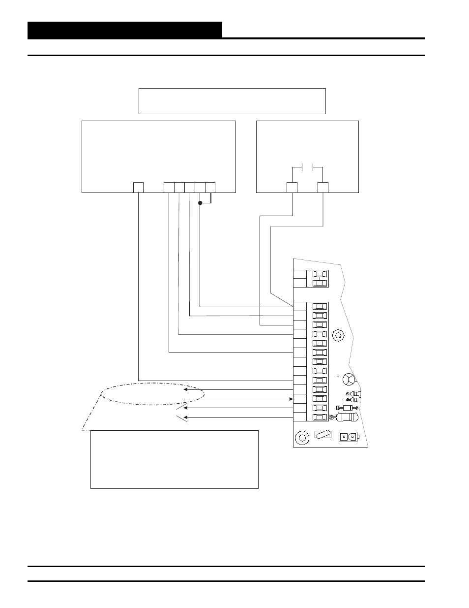
Dehumidistat (24VAC)
Normally Open
DH
DH
Single-Stage Thermostat
1-Cool / 1-Heat
(24VAC)
W1
Y1
RH
RC
C
G
24VAC Power Supply
24VAC to Economizer
Clogged Filter Indicator
(Outputs 24VAC)
24VAC
GND
HB Controller Terminal Block
Note:
The economizer will not have 24VAC to the actuator
without installing a jumper wire between A1 and A2.
If a device needs to disable the economizer, install a
normally closed contact between A1 and A2.
If a device needs to enable the economizer, install a
normally open contact between A1 and A2.
C
(GND)
Single Stage T-stat Wiring For HB Units
With 2 Stage Cooling & 3 Stage Heating
Figure 5: Single-Stage T-Stat Wiring for HB Units with 2-Stage Cooling & 3-Stage Heating
Controller Installation & Wiring