Appendix, 39 hb controller technical guide – Orion System HB Controller User Manual
Page 39
Appendix
39
HB Controller Technical Guide
Appendix
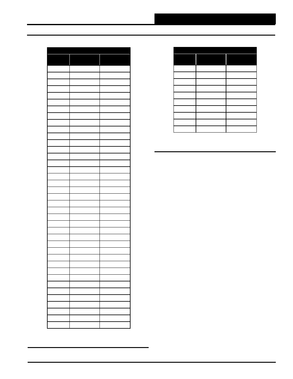
Temperature to Resistance/Voltage Chart
Temp
(
°F)
Resistance
(Ohms)
Voltage @
Input (VDC)
-10
93333
2.98
-5
80531
2.94
0
69822
2.89
5
60552
2.83
10
52500
2.77
15
45902
2.71
20
40147
2.64
25
35165
2.57
30
30805
2.49
35
27140
2.41
40
23874
2.33
45
21094
2.24
50
18655
2.15
52
17799
2.11
54
16956
2.08
56
16164
2.04
58
15385
2.00
60
14681
1.96
62
14014
1.93
64
13382
1.89
66
12758
1.85
68
12191
1.81
69
11906
1.79
70
11652
1.78
71
11379
1.76
72
11136
1.74
73
10878
1.72
74
10625
1.70
75
10398
1.68
76
10158
1.66
78
9711
1.63
80
9302
1.59
82
8893
1.55
84
8514
1.52
86
8153
1.48
88
7805
1.45
90
7472
1.41
95
6716
1.33
100
6047
1.24
Temperature to Resistance/Voltage Chart
Temp
(
°F)
Resistance
(Ohms)
Voltage @
Input (VDC)
105
5453
1.16
110
4923
1.09
115
4449
1.02
120
4030
.95
125
3656
.88
130
3317
.82
135
3015
.76
140
2743
.71
145
2502
.66
150
2288
.61
Table 14: Temperature Sensor - Voltage &
Resistance for Type III Sensors
Table 14, continued: Temperature Sensor - Voltage
& Resistance for Type III Sensors
Thermistor Sensor Testing Instructions
1.) Use the resistance column to check the thermistor sensor while dis-
connected from the controllers (not powered).
2.) Use the voltage column to check sensors while connected to powered
controllers. Read voltage with meter set on DC volts. Place the “-” (mi-
nus) lead on GND terminal and the “+” (plus) lead on the sensor input
terminal being investigated.
If the voltage is above 3.3 VDC, the sensor or wiring is “open.” If the
voltage is less than 0.05 VDC, the sensor or wiring is shorted.