Important – Remotec ZTS-110 V3.14 User Manual
Page 9
9
Important!
If you will be powering the ZTS‐110 with 24Vac:
Connect the “24Vac Common” (typically the black wire/terminal) and “24Vac Power” (typically
the Red wire/terminal) from the HVAC system to the ZTS‐110 HVAC System terminal block “C”
and “RH” or “RC” terminals (see the following explanation, these may be jumpered together).
Common or Split Transformer Systems:
Most HVAC systems have a common heating and cooling transformer. You must insert a jumper
wire to tie the RH and RC inputs together for this configuration. If you have a system with
separate heating and cooling transformers, do not insert a jumper wire between RC and RH.
When wiring split systems, wire the heating systems “24Vac Power” (red wire) to the ZTS‐110
“RH” terminal, and wire the cooling systems “24Vac Power” to the ZTS‐110 “RC” terminal. Also
wire the cooling systems “24Vac Common” to the ZTS‐110 “C” terminals.
Note: Do not split RC/RH for Heat Pump systems!
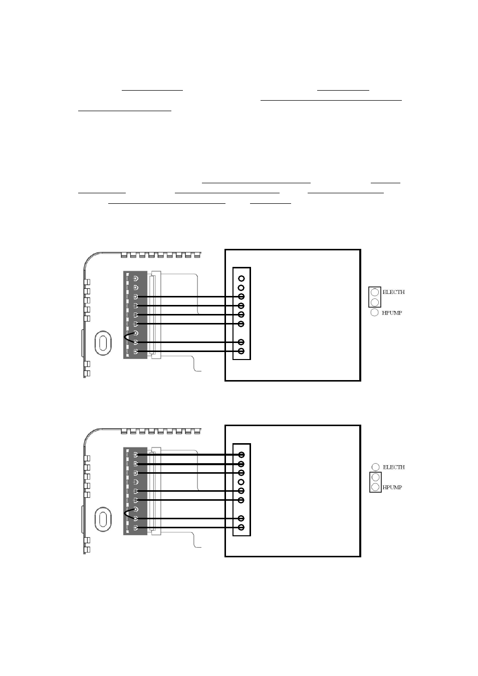
Figure 4. Non‐heat pump (Standard Gas or Electric) HVAC system wiring
Figure 5. Heat pump HVAC system wiring
O
B
W2
W1
G
Y
RC
RH
C
C - 24Vac Common
R - 24Vac Power
Y - Compressor
G - Fan
W1 – 1
st
stage heater
W2 – 2
nd
stage heater
Black
Red
Yellow
Green
White
Brown
Standard HVAC System
O
B
W2
W1
G
Y
RC
RH
C
C - 24Vac Common
R - 24Vac Power
Y - Compressor
G - Fan
W2 – 2
nd
stage heater
Black
Red
Yellow
Green
Brown
O - Cool changeover (heat pump)
Heat Pump HVAC System
ZTS-110
B - Heat changeover (heat pump)
Blue
Orange
ZTS-110
J2
J2