TE Technology TC-36-25-RS485 User Manual
Page 20
20
2.0 Controller Setup
NOTE: If you plan to have more than one controller on the network, a unique address number must first be
assigned to each controller to prevent communication errors. It is recommended that each controller be
programmed with a unique address one at a time. Once done, the controllers can then be networked
together.
If you plan on using only one controller on the network, then you can leave the default address as is.
However, if you add another controller to the network, you must take steps to assign a different address to
the new controller before using, or communication errors will result.
1. When only one controller will be on the network at a time:
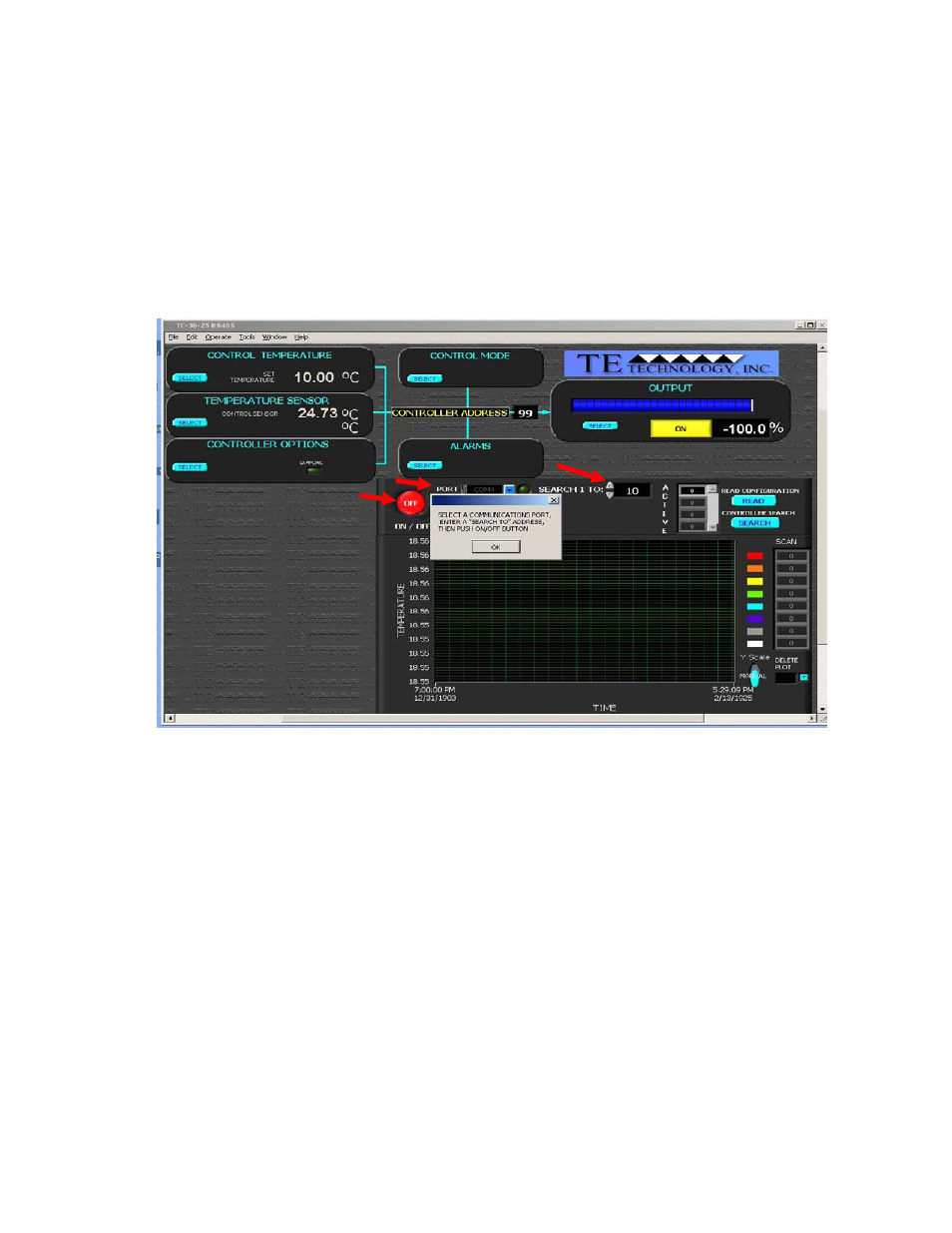
When the software is first started, it should prompt you to select the communications port to which the controller
is connected. It should then prompt you to enter an address number corresponding to a range of controller
addresses to search for. For new controllers, enter “98” [without the quotes] in the SEARCH ADDRESS RANGE
(indicated below), and then click the blue START button. For an existing controller, enter the address for that
controller. The software should then find and list the controller with its corresponding address (usually 98 for a
new controller) in the CONTROLLER LIST.
2. When a controller is being added to an existing network:
Before applying power to the new controller and adding the controller to the network, place a jumper between
JP2‐1 and JP2‐4. Also, if the new controller being added will be at the end of the network, make sure the new
controller is the only one with a terminating resistor across JP4‐1 and JP4‐2. See Multiple Controller Wiring (RS485)
Diagram for further details.
If the software is currently running the existing network, apply power to the new controller, and enter “99”
[without the quotes] in the SEARCH ADDRESS RANGE. Then click the CONTROLLER SEARCH button to search for the
new controller. When the jumper is added to the controller, it automatically assumes address 99. You can then
assign a new address (see Section 2.4.6) to that controller (make sure EEPROM WRITE ENABLED is checked; see
Section 2.4.1), remove power, remove the jumper, re‐apply power, and communicate with the controller with the
newly assigned address. You can also use this method if you have inadvertently assigned the same address to two
or more controllers and need to reassign a new address.
START OF PROGRAM,
1. SELECT COM PORT
2. ENTER SEARCH RANGE
3. PRESS “ON/OFF” BUTTON
3
1
2