Expansion connector wiring diagram – TE Technology TC-36-25-RS485 User Manual
Page 36
36
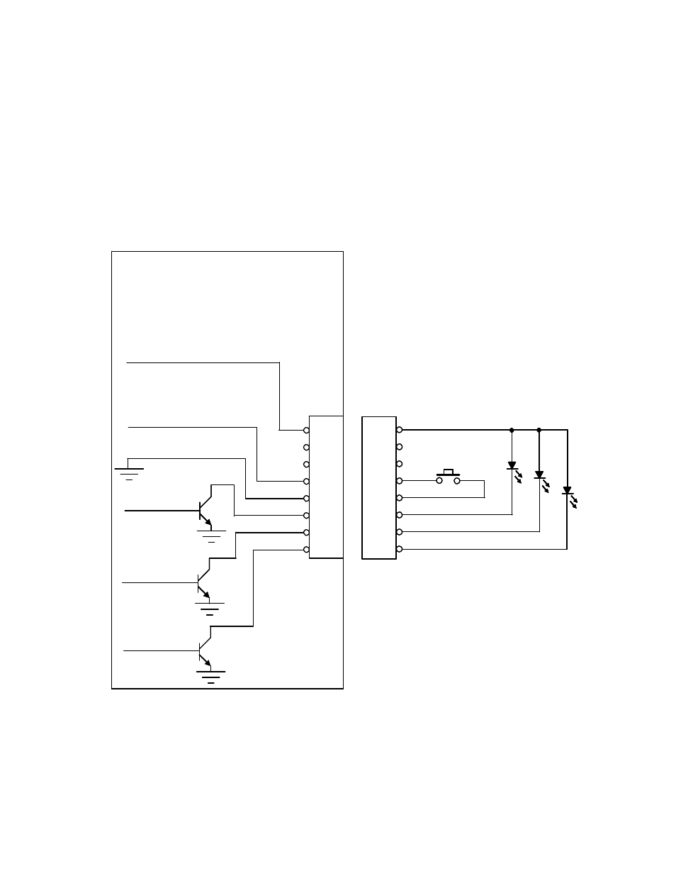
Expansion Connector Wiring Diagram
Note: The 25 mA current source is a true current source. Maximum compliance voltage is approximately V+, the input
voltage to the temperature controller. No external current limit resistors are needed for the LED. The LED must be
capable of being driven with a 25 mA continuous current.
8
7
6
5
4
3
2
1
Expansion Connector
Molex 22-23-2081
25 mA Current Source
Alarm Cancel
Input Common
High Alarm
Low Alarm
No Alarm
JP5
8
7
6
5
4
3
2
1
Customer- supplied
Connector
Note: Pins 6 and 7 not functionally defined.
Please do not connect.
8
7
6
5
4
3
2
1
Expansion Connector
Molex 22-23-2081
25 mA Current Source
Alarm Cancel
Input Common
High Alarm
Low Alarm
No Alarm
JP5
8
7
6
5
4
3
2
1
Customer- supplied
Connector
Note: Pins 6 and 7 not functionally defined.
Please do not connect.