TE Technology TC-36-25-RS485 User Manual
Page 28
28
2.6
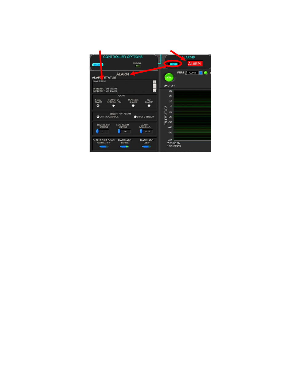
ALARMS
The alarm status and controls are viewed and set in this section.
2.6.1 ALARM STATUS
Any alarm that occurs in the controller whose address is in the address box will be displayed in the alarm status
box. When there is an active alarm the ALARM indicator light will blink.
The possible alarm conditions are:
HIGH ALARM: the temperature is greater than the HIGH ALARM SETTING
LOW ALARM: the temperature is lower than the LOW ALARM SETTING
COMPUTER CONTROLLED ALARM: the user has activated the alarm relay via the software
OVER CURRENT DETECTED: the TE device attempted to draw more current than allowed the OVER CURRENT SET
OPEN INPUT1: there is a problem with the primary temperature sensor
OPEN INPUT2: there is a problem with the secondary temperature sensor
DRIVER LOW INPUT VOLTAGE: the controller does not have a high enough voltage to properly operate
2.6.2 ALARM MODE
a) FIXED VALUE ALARMS: permits the setting of a fixed, absolute temperature either above or below the sensor
temperature or both.
b) COMPUTER CONTROLLED: provides for user activation of the alarm relay via the computer software. This is
turned on and off with the ALARM LATCH ENABLE button.
c) SET TRACKING ALARMS: allows an alarm to be set with respect to the set temperature. It will move accordingly
with a change of the temperature setting. This option can be used for a high alarm, low alarm, or both settings.
d) NO ALARMS PICKED: no alarm condition will be monitored.
e) The “Expansion Connector Wiring Diagram” shows how customer‐supplied LED’s can be installed to externally
signal various alarm conditions as well.
Associated with the ALARM TYPE configuration are the HIGH ALARM SETTING box, LOW ALARM SETTING box, and
the ALARM DEADBAND box. If an alarm type has been selected, enter the desired high and low temperature
values that you want to have trigger an alarm condition. The ALARM DEADBAND option sets the hysteresis of the
alarm values from 0.1 degrees to 100 degrees.
2.6.3 SENSOR FOR ALARM
a) CONTROL SENSOR: if this is selected, the primary sensor is used for monitoring alarm conditions.
b) INPUT 2 SENSOR: if this is selected, the secondary sensor is used for monitoring alarm conditions. This requires
that a secondary thermistor be installed, and a potentiometer or voltage/current levels cannot be used for
adjusting the set point temperature.
ALARM INDICATOR
ACTIVE ALARMS
ALARM INDICATOR
ACTIVE ALARMS