TE Technology TC-36-25-RS485 User Manual
Page 30
30
2.7
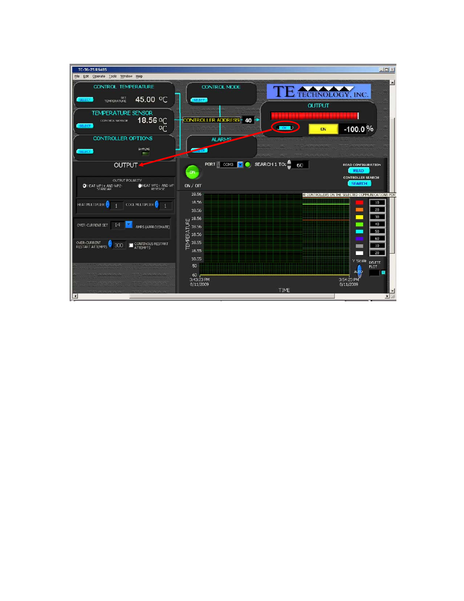
OUTPUT
OUTPUT ON/OFF:
a) OFF: output power to the TE device is shut off.
b) ON: output power to the TE device is enabled and the controller will begin controlling to the set point
temperature (if possible).
For the initial setup, (prior to connecting a TE device), turn output to OFF.
2.7.1 OUTPUT POLARITY HEAT: WP1+ AND WP2‐ or HEAT WP2+ AND WP1‐
This selection establishes the polarity for the heating mode of the thermoelectric cooler. It allows you to reverse
the current flow in the TE device without having to change the wiring.
NOTE: For TE Technology’s standard products, the TE+ (red) wire should be attached to WP2 and the TE‐ (black)
wire should be attached to WP1 as shown in the “Controller Wiring Diagram.” The OUTPUT POLARITY should then
be set to HEAT WP1+ and WP2‐. Again though, do NOT connect the TE device at this time.
2.7.2 HEAT SIDE MULTIPLIER
This is a 0.00 to 1.00 numerical multiplier that compensates for the non‐symmetrical response of the
thermoelectric cooler between the heat and cool modes. When the controller is in heating mode it takes the
computed PID output power value and multiplies it by this multiplier to derive the actual output level. Setting the
value to 0 makes the controller a “cool only” controller.
2.7.3 COLD SIDE MULTIPLIER
This is a 0.00 to 1.00 numerical multiplier that compensates for the non‐symmetrical response of the
thermoelectric cooler between the heat and cool modes. When the controller is in cooling mode it takes the
computed PID output power value and multiplies it by this multiplier to derive the actual output level. Setting the
value to 0 makes the controller a “heat only” controller.