Refer to – Verilink PRISM 3000 (34-00184) Product Manual User Manual
Page 13
Installation
2-3
PRISM 3000
2.5
Data Port Connections
The PRISM 3000 is available with 2 or 4 high speed data
ports installed in Ports 1 through 4 on the rear panel (refer to
). Each slot may contain two ports.
The ports are configured as data communications equipment
(DCE) for connection to data terminal equipment (DTE) and
may be equipped with any combination of V.35 or EIA530
compatible interfaces. Pin assignments for both the V.35 and
EIA530 interfaces are given in Appendix A.
Warning: FCC rules require that interconnecting
cables carrying high speed data be shielded appropri-
ately in order to minimize radio frequency interference.
2.6
T1 DTE Connection
The PRISM 3000 is supplied with a T1 DTE port, which
functions only if the unit is equipped with the T1 DTE inter-
face card. This function provides a DSX1 level interface
which allows the user to pass DS0 channels through the unit
from the network side to other T1 oriented equipment via
the T1 DTE port.
A typical installation divides the channel usage so that DS0
channels carrying high speed data are mapped to the high
speed data ports while voice channels are passed to a chan-
nel bank or a PABX connected to the T1 DTE port.
The DTE DSX1 line build out level should be set as shown
in ‘DSX Level’ in
Section 3.4 on page 3-4
. The T1 DTE
physical interface is a standard RJ48C 8 -pin modular jack
with the following pinout assignments.
2.7
Network Connection
The network side of the PRISM 3000 is referred to as the
network interface. This interface contains an ALBO (auto-
matic line build out) which allows the unit to be located a
substantial distance away from the telco network interface
with a receive signal level down to -27 dB.
The network interface LBO level should be set as instructed
in ‘Line Build Out’ in
Section 3.3 on page 3-3
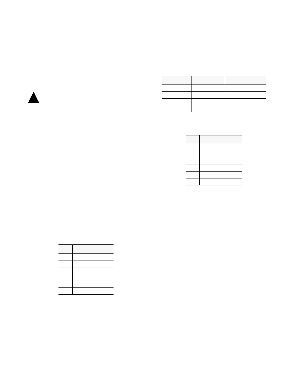
. Maximum
suggested cable lengths for the connection from the unit to
the network are listed in the following table. Calculations
are based on a cable temperature of 70° F, 0.083 uF/mile
capacitance, a 27 dB loss, and a 100 ¾, non-loaded, twisted
pair cable. PIC refers to Plastic Insulated Cable.
The network physical interface is a standard RJ48C 8-pin
modular jack with the following pinout assignments.
Network Disconnection: In accordance with FCC Rules,
Part 68.218 (b), the user must notify the telephone company
prior to disconnecting the PRISM 3000.
2.8
Alarm Connection
Alarm conditions detected by the PRISM 3000 are conveyed
at the isolated ‘A
LARM
R
ELAY
’ output contacts on the rear
panel. NC (Normally Closed) and NO (Normally Open)
refer to the alarm contact’s relationship to C (Common)
under a ‘no alarms’ condition.
Alarm connections are made to the terminal strip using a
22-gauge stranded, or similar, wire. The ‘Normally Closed’
alarm connects to NC & C. The ‘Normally Open’ alarm
connects to NO & C. Contacts are rated at 0.6 Amp AC or
2.0 Amp DC. Alarm parameters are discussed in
Section
4.6.2 on page 4 -11
.
2.9
External Clock Connection
If the PRISM 3000 is to receive its timing source from a
user supplied clock other than the DTE or T1 lines, the ‘Sta-
tion Clock’ input must be connected on the rear panel. This
input is designed to accept TTL or bipolar signal levels. The
Pin
T1 DTE Interface
1
Data Out
2
Data Out
3, 6
Not Used
4
Data In
5
Data In
7, 8
Chassis Ground
!
Cable Type
Loss per 1000'
Max Cable Length
26 gauge PIC
6.8 dB
4,400 ft
24 gauge PIC
5.4 dB
5,500 ft
22 gauge PIC
4.2 dB
7,100 ft
19 gauge PIC
3.0 dB
10,000 ft
Pin
T1 NET Interface
1
Data In
2
Data In
3, 6
Not used
4
Data Out
5
Data Out
7, 8
Chassis Ground