Verilink PRISM 3000 (34-00184) Product Manual User Manual
Page 16
PRISM 3000
2-6
Installation
The user must attach the appropriate MAU (media attach-
ment unit) for connection to the existing LAN medium.
MAUs are available for connection to 10BASE-5 (Thick
Net), 10BASE-2 (Thin Net), and 10BASE-T (twisted pair).
SNMP configuration should be performed prior to connect-
ing the PRISM 3000 to the LAN interface. This is described
in
Section 3.6 on page 3-7
and
Section 4.6.5 on page 4 -13
.
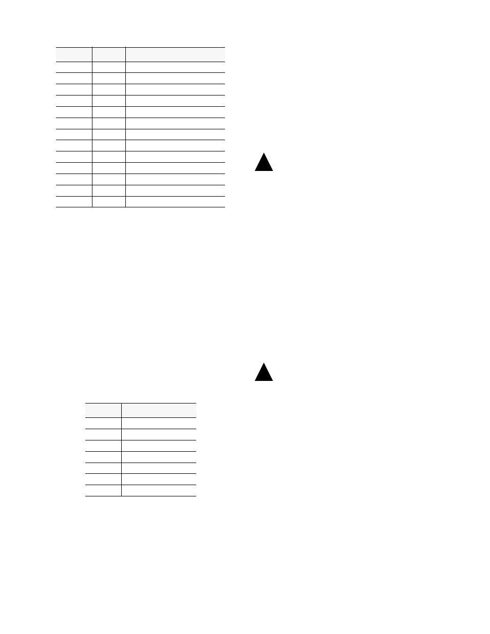
Token Ring: The Token Ring interface is designed to oper-
ate on both 4 and 16 Mb/s networks. For 4 Mb/s operation,
jumper J3 must be strapped across pins 1 and 2. For opera-
tion at 16 Mb/s, jumper J3 must be strapped across pins 2
and 3. The Token Ring interface consists of a 9-pin female
connection compatible with shielded twisted pair (STP)
cable and complies with ISO/IEC 8802-5 (formerly IEEE
802.5). The pinout assignments are as follows:
Connection to unshielded twisted pair (UTP) cable may be
accomplished using an appropriate STP to UTP media filter/
adapter (TxPORT part #
9-1001-056-1
). After connec-
tion to the Token Ring LAN, the unit must be powered down
and then back up to allow the interface to perform a self-test
on the network.
2.11 Power Connection
The PRISM 3000 is factory equipped for one of three pow-
ering options as required by the user. The 110 VAC version
is supplied with a standard three-prong AC cord. The 220
VAC version is supplied with an unterminated cord. Both
AC versions are fused at 1.0 A.
The DC power version is equipped with terminal blocks for
power connection and is fused at 2.0 A. In all cases, a
proper ground should be connected to the ‘GND’ terminal.
Remove power before checking fuses.
NOTE: On power up, the board initialization sequence
causes a delay. During this period, the message on the
front panel shows ‘
Calculating
Checksum
’. Each
voice card adds 6 seconds to the delay.
2.11.1 AC Power Connection
1)
Connect the AC power cord to an appropriate AC power
receptacle.
2)
Set the rear panel power ON/OFF switch to the ‘ON’
position (labeled ‘
l
’). The green power LED on the front
panel should light after the LED initialization sequence
ends. If the indicators do not light, recheck the power con-
nections and the primary AC circuit breaker. Make sure the
ON/OFF switch is in the ON position.
2.11.2 DC Power Connection
Connect the ground lead before applying power
to the unit.
1)
Connect a ground lead (18 to 20-gauge) to the ‘GND’
terminal. In many cases the 48V return is also ground. In
that case, both ‘RET’ and ‘GND’ should be connected to
ground.
2)
Connect the 48 VDC lead (22-gauge) to ‘DCV’. Con-
nect the return lead to ‘RET’.
3)
Set the rear panel power switch to the ‘ON’ position.
The green power LED on the front panel should light after
the LED initialization sequence ends. If the indicators do
not light, recheck the power connections and make sure the
ON/OFF switch is in the ‘ON’ position.
Contact
Circuit
Ethernet Interface
3
DO -A
Data Out (Ckt. A)
10
DO -B
Data Out (Ckt. B)
11
DO-S
Data Out (Ckt. Shield)
5
DI-A
Data In (Ckt. A)
12
DI-B
Data In (Ckt. B)
4
DI- S
Data In (Ckt. Shield)
2
CI-A
Control In (Ckt. A)
9
CI-B
Control In (Ckt. B)
1
CI-S
Control In (Ckt. Shield)
6
VC
Voltage Common
13
VP
Voltage Plus
14
VS
Voltage Shield
Shell
PG
Protective Gnd (conductive shell)
Pin
Token Ring Function
1
Data In (A)
6
Data In (B)
9
Data Out (A)
5
Data Out (B)
3
+ 5 Volts
2, 4, 7, 8
Signal Ground
10, 11
Chassis Ground
!
!