Ed in, Network plb, Figure 4-2 loopback diagrams network llb – Verilink PRISM 3000 (34-00184) Product Manual User Manual
Page 36: Network mlb
PRISM 3000
4-8
Terminal Operation
Normal Operation
Network Interface
To Network
From Network
RJ48C
Framer /Deframer
Multiplexor
Receivers/Drivers
Receivers /Drivers
BERT Generator /
Detector
DTE (EIA530 or V.35)
(100' max.)
Framer /Deframer
DTE (DSX1)
RJ48C
DSX1, 1'-655'
to cross-connect
From
NET
To
NET
To
NET
From
NET
5
4
2
1
To
Ports
From
Ports
5
4
2
1
Network PLB
Network Interface
Framer /Deframer
Multiplexor
Receivers /Drivers
NET
PLB
Receivers /Drivers
BERT Generator /
Detector
All ones
to DTE
EIA 530 or V.35
(100' max.)
Framer /Deframer
DTE (DSX1)
RJ48C
DSX1, 1'- 655'
to cross-connect
From
NET
To
NET
To
NET
From
NET
5
4
2
1
To Network
From Network
RJ48C
5
4
2
1
To
Ports
From
Ports
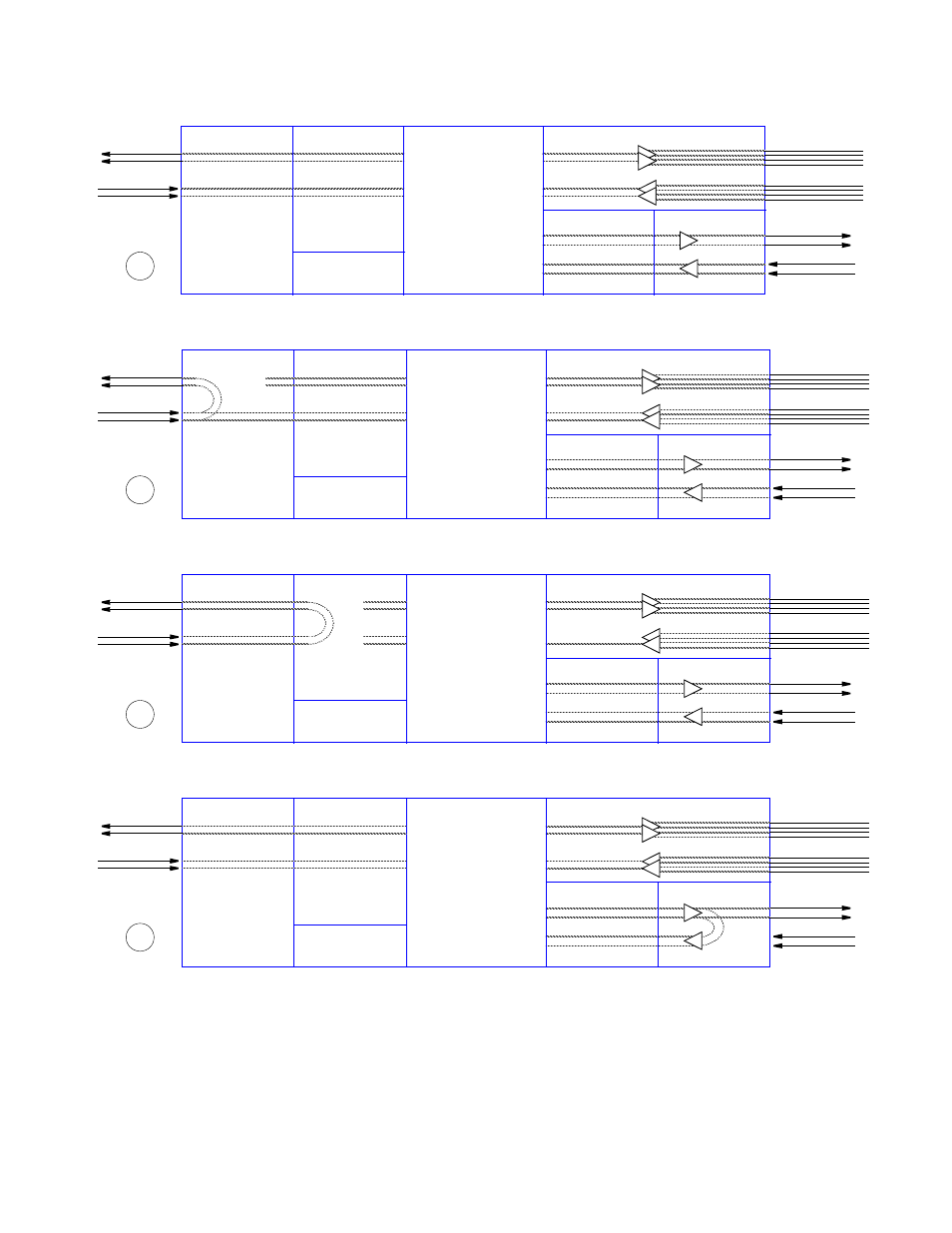
Figure 4-2
Loopback Diagrams
Network LLB
Network Interface
Framer /Deframer
Multiplexor
Receivers /Drivers
Receivers /Drivers
BERT Generator /
Detector
EIA 530 or V.35
(100' max.)
Framer /Deframer
DTE (DSX1)
RJ48C
DSX1, 1'- 655'
to cross-connect
From
NET
To
NET
To
NET
From
NET
5
4
2
1
To Network
From Network
RJ48C
5
4
2
1
To
Ports
From
Ports
NET
LLB
Network MLB
Network Interface
Framer /Deframer
Multiplexor
Receivers /Drivers
Receivers /Drivers
BERT Generator /
Detector
EIA530 or V.35
(100' max.)
Framer /Deframer
DTE (DSX1)
RJ48C
DSX1, 1'- 655'
to cross-connect
From
NET
To
NET
To
NET
From
NET
5
4
2
1
NET
MLB
To Network
From Network
RJ48C
5
4
2
1
To
Ports
From
Ports
1
2
3
4
1)
Normal Operation: This diagram depicts the unit’s nor-
mal operating mode.
2)
NET LLB: The network ‘line loopback’ command
loops data received from the network back toward the net-
work. Received data is passed through to the DTE ports.