Verilink PRISM 3000 (34-00184) Product Manual User Manual
Page 15
Installation
2-5
PRISM 3000
elements is connected in an NMS chain, the EM8000 may
be connected to the supervisory port of any one of the ele-
ments. This element can then route messages onto the NMS
chain to reach the other elements. The call on alarm (COA)
feature works through the supervisory port only.
The supervisory port is an independent serial interface into
the PRISM 3000 and plugging into it does not interrupt the
NMS port traffic. The supervisory port bit rate must be set
by the front control panel (refer to ‘System Utilities’,
Sec-
tion 3.8 on page 3 -10
).
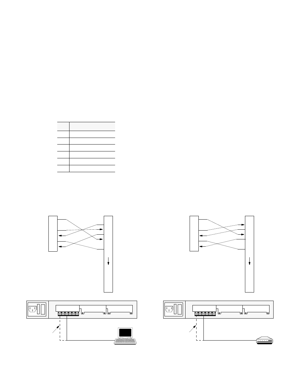
The physical connection is a 6-pin modular jack with the
following pinout assignments. The port is a serial RS232
DCE port configured for 8 bits, no parity, and 1 stop bit.
Pin
SUPV Port Interface
1
Control Out
2
Signal Ground
3
Data Out
4
Data In
5
Signal Ground
6
Control In
2.10.3 LAN SNMP Connection
The PRISM 3000 may be equipped with an optional Ether-
net or Token Ring interface for connection to the user’s
LAN (local area network). The unit’s SNMP (Simple Net-
work Management Protocol) agent can then be programmed
to take advantage of the centralized status monitoring and
alarm reporting capability of SNMP managed networks. The
LAN interface is connected to Slot 1 on the rear panel.
Ethernet: The Ethernet interface consists of a 15-pin
female AUI (attachment unit interface) connection compli-
ant with ISO/IEC 8802-3 standards (formerly IEEE 802.3).
The pinout assignments are as follows:
l
0
RS232 to Terminal
Terminal
NMS IN may
also be used
Modem
NMS IN may
also be used
RS232 to Modem
l
0
(PN # 9 - 1001 -028 -1)
(PN # 9 - 1001 - 027- 1)
Control Out
1
2
Data Out
3
Data In
4
Signal Gnd
5
Control In
6
Figure 2-3
Supervisory Port to Terminal Connection
Figure 2-4
Supervisory Port to Modem Connection
Terminal (DTE)
Supervisory Port
20
21
22
23
24
1
2
TXD
3
RXD
4
RTS
5
CTS
6
7
Signal Gnd
8
DB25
Control Out
1
2
Data Out
3
Data In
4
Signal Gnd
5
Control In
6
Modem (DCE)
Supervisory Port
20
21
22
23
24
1
2
TXD
3
RXD
4
RTS
5
CTS
6
7
Signal Gnd
8
DB25
PRISM 3000 Rear Panel
PRISM 3000 Rear Panel