Section 3.5, 5 dte port configuration – Verilink PRISM 3000 (34-00184) Product Manual User Manual
Page 21
Operation
3-5
PRISM 3000
This menu also displays ‘
Rem
Comm
’ (channels assigned as
remote communication channels) and ‘
Port
X
’ (channels
assigned to ports are indicated as Port 1 to Port 4.
Alarm Thresholds: The PRISM can generate alarm condi-
tions based on alarm thresholds set for periods of 15 min-
utes (900 seconds). A field set to ‘
0
’ causes the unit not to
alarm on that statistic. To effectively disable alarm report-
ing, set all fields to ‘
0
’.
DTE OOFS: Sets the DTE out of frame seconds thresh-
old. The default value is 0 (disabled).
3.5
DTE Port Configuration
The ‘DTE Port Configuration’ display sets the operating
parameters for each of the high speed ports and the RS232
port. The unit does not allow conflicting configurations for
the DTE ports. Therefore, the selections for each menu item
are restricted to those that do not conflict with the configura-
tion of other high speed ports or the T1 DTE Port. The
default is all ports disabled.
DTE Port Configuration Screen
When channel assignment changes are made to the high
speed ports, the remote communication link, or the T1 DTE,
the PRISM reestablishes the mapping of all channels. This
interruption to traffic will normally result in a brief burst of
data errors on other ports.
Port Rate Multiplier: The PRISM can operate at any data
rate that is a multiple of 56 or 64 kb/s. If ‘
N x 64K
’ is
selected, the ones density requirements of the T1 network
line must be ensured. If ‘
N x 56K
’ is selected, ones density
for the selected DS0 channel is maintained. When set to
‘
DISABLE
’, the port is not used and no other configuration
choices for that port are available.
Port Rate: The ‘
N
’ parameter selects the required port bit
rate in increments of 56 or 64 kb/s, depending on the selec-
tion in ‘
Port
Rate
Multiplier
’. The ‘N’ multiplier
ranges in value from 0 to 23. For example, if N is 23 and the
base rate is 64 kb/s, the data rate is 1472 kHz (64k x 23).
Starting Channel Number: This field selects the starting
channel in the 24-channel DS1 bit stream. The unit automat-
ically assigns the channels which follow according to the bit
rate and the mode selected in ‘
DS0 Channel
Assign-
ment
’. If some channels are already allocated, the starting
channel is adjusted to the first block of idle channels that
matches the bandwidth to be mapped. The starting channel
should be checked before bandwidth is allocated.
DS0 Channel Assignment: Selects whether the DTE chan-
nel assignment will be made as a ‘
CONTIGUOUS
’ group or
as ‘
ALTERNATE
’ channels. Selecting ‘
ALTERNATE
’ will
assure ones density.
Port Transmit Clock: This field is used to select the clock
that the unit will use to sample the data transmitted from the
DTE. When set to ‘
INTERNAL
’, the data is sampled directly
with the transmit data clock that is also supplied to the DTE
as Transmit Clock. The ‘
EXTERNAL
’ option uses the exter-
nal clock from the DTE. The ‘
OVERSAMPLED
’ option is
used to operate the port as a low speed asynchronous port.
In this mode, the port rate should be set to at least 3 times
the asynchronous data rate (depending on the degree of
allowable distortion for the particular DTE equipment used).
Invert Data: In the invert mode (
YES
), transmit and receive
data are inverted at the port interface. This function may be
used as a means of guaranteeing ones density when the data
is composed of SDLC type protocols. The choices are ‘
YES
’
and ‘
NO
’.
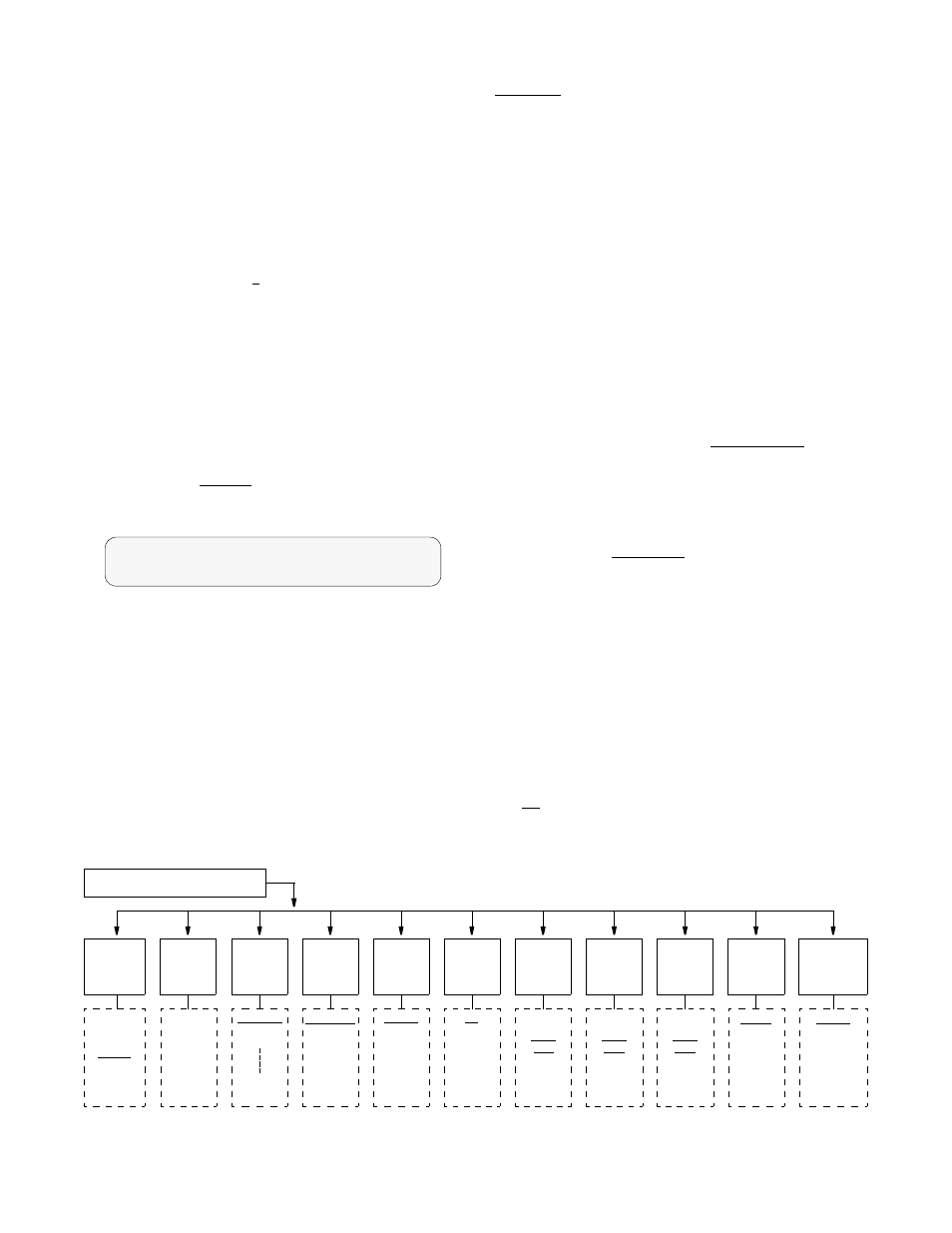
DTE Port Configuration
Port Rate ... 64Kx24=1536 kHz
<
Port
Rate
Multiplier
Port
Rate
Starting
Channel
Number
DS0
Channel
Assign.
Port
Transmit
Clock
Invert
Data
CTS
Control
DSR
Control
DCD
Control
N x 56K
N x 64K
Disable
Selects
the ‘N’
multiplier
for
‘Port Rate
Multiplier’
(0 - 24).
Channel 1
Channel 2
Channel 24
Contiguous
Alternate
Internal
External
Over-
sampled
No
Yes
Internal
Force
True
Force
False
Internal
Force
True
Force
False
Internal
Force
True
Force
False
V.54
Loop
Enable
Disable
DTE Port Configuration Menu Diagram
Slot X Port Y Config Menu
Alarm on
DTR Loss
Disable
Enable