Section 3.3, 2 main menu display, 3 t1 net configuration – Verilink PRISM 3000 (34-00184) Product Manual User Manual
Page 19
Operation
3-3
PRISM 3000
When the element is a user selectable function, pressing
<Select> moves the cursor to the right with the arrow point-
ing left (
<
) as
seen in the second screen
below.
Example of Cursor Movement
This allows the user to scroll through the options available
for that function using the arrow keys. Pressing <Select>
again sets that parameter. Pressing <Exit> returns the cursor
back to the left. The cursor will not appear when status-only
elements are displayed.
NOTE: To return to the previous screen without chang-
ing a parameter, press <Exit>. Do not press <Select>.
Pressing <Exit> again returns the previous screen.
3.2
Main Menu Display
The ‘Main Menu’ screen is the first level of access for all
the functional menus available to the user. To activate any of
these menus or submenus, use the methods described in
.
The ‘Main Menu’ diagram is shown on
. The sec-
tion and page numbers are provided in case the user needs to
refer to a specific topic.
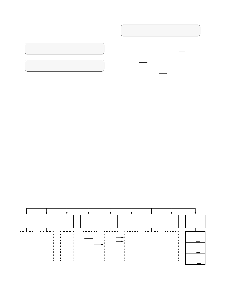
3.3
T1 NET Configuration
The ‘T1 NET Configuration’ screen allows the following
network configuration parameters to be set.
T1 NET Configuration Screen
Framing Type: Selects the framing for the network side of
the DSU/CSU. The choices are ‘
D4
’ and ‘
ESF
’.
Line Code: Sets the network side line coding. The choices
are ‘
AMI
’ and ‘
B8ZS
’.
Line Build Out: Sets the line build out for the network
interface. The choices are: ‘
0
dB
’, ‘
-7.5
dB
’, ‘
-15
dB
’,
and ‘
-22.5
dB
’.
Timing: Sets the timing source to synchronize the unit’s
internal timing generators. In all cases, slips are controlled
to occur on frame boundaries at the network and/or DSX1
ports when timing synchronization is lost. The choices are:
INTERNAL: The PRISM unit’s internal frequency stan-
dard is used for all timing.
NETWORK: Timing is derived from the network recov-
ered clock (the most common selection for most applica-
tions).
T1 DTE: The unit synchronizes to the clock recovered
from the DSX1 T1 DTE port. This selection only appears
on units equipped with the T1 DTE option.
STATION: Timing is derived from a bipolar or TTL com-
patible clock supplied to the unit via the rear panel ‘STA
CLK’ connector. When this mode is selected, the timing
rate must also be set from ‘
Station
Input
Timing
’.
PORT 1, 2, 3, or 4: Timing is synchronized to the exter-
nal terminal timing clock supplied from the DTE and con-
nected to the selected port. Selections will only appear for
ports which are installed on the unit.
Station Input Timing: This field selects the input timing
and only appears when ‘
Station
’ has been selected from
T1 NET Configuration
>
Framing Type ..........
ESF
T1 NET Configuration
Framing Type ..........
ESF
<
T1 NET Configuration
Line Code .............
AMI
<
Framing
Type
Line
Code
Line
Build
Out
Timing
ESF
D4
AMI
B8ZS
0 dB
-7.5 dB
-15 dB
- 22.5 dB
Internal
Network
T1 DTE
Station
Port 1
Port 2
Port 3
Port 4
Station
Input
Timing
1.544 MHz
Nx56 K
Nx64 K
(‘Station’
Timing
must be
selected)
Zero
Suppress
Enable
Disable
PRM
Enable
Enable
Disable
Alarm
Thresholds
Station
Timing
Selects the
‘N’ multi-
plier (1 -
24) for the
Input
Timing
.
Alarm Reset 030
ES 045
SES 005
LOSS 005
OOFS 005
UAS 000
RAS 000
AISS 000
BPVS 000
T1 NET Configuration Menu Diagram