Verilink PRISM 3000 (34-00184) Product Manual User Manual
Page 42
PRISM 3000
4-14
Terminal Operation
SNMP traps. When a network alarm occurs, the unit sends a
trap message to up to 6 destinations on the user’s network.
The trap message is formatted per RFC 1157. The generic
trap type is ‘enterpriseSpecific’ (generic-trap = 6).
When an alarm group is defined to report via SNMP, up to 6
Trap IP addresses can be assigned. The PRISM will report
each alarm by transmitting an SNMP ‘Trap’ to each Trap IP
address. T1 network problems often cause more than one
alarm type. In these cases, multiple trap messages are gener-
ated, each with a different specific trap type. The specific-
trap field of each trap message is set to one of the values
shown in the ‘Trap Definition’ table on the previous page.
The following five menu items require the entry of up to 255
characters identifying the appropriate group, person, device
function, or unit location.
Read Community: This display accepts a character string
identifying the group authorized to perform read operations.
The default setting is ‘
public
’.
Write Community: This display accepts a character string
identifying the group authorized to perform write opera-
tions. The default setting is ‘
private
’.
System Contact: This display accepts a character string
identifying the person responsible for a network device. The
default setting is ‘
no
system
contact
’.
System Name: This display accepts a character string iden-
tifying the functionality of the network device. The default
setting is ‘
no
system
name
’.
System Location: This display accepts a character string
identifying the physical location of network device. The
default setting is ‘
no
system
location
’.
3000 DSU x.xx/x.xx
PRISM 3000 Date:
MM/DD/YY
No Far End Response
Boston: (232) Time:
HH:MM:SS
--------------------------- Voice Port Configuration ---------------------------
Element: (NEAR)
Slot: (3)
Card Type: 4 Wire E&M
Port DS0 Mode State Name/ID Sig. Tx Gn. Rx Gn.
-------------------------------------------------------------------------------
A (13) [ACTIVE] BUSY (DS0 13 ) [FXS/LS] [ 0dB] [ -6dB]
B (14) [ACTIVE] BUSY (DS0 14 ) [FXS/GS] [ 0dB] [ -6dB]
C (15) [ACTIVE] BUSY ( ) [MEG/LS] [ 0dB] [ -6dB]
D (16) [ACTIVE] BUSY ( ) [MEG/GS] [ 0dB] [ -6dB]
E (17) [ACTIVE] BUSY ( ) [PLAR ] [ 0dB] [ -6dB]
F (18) [SPARE ] IDLE ( ) [FXS/LS] [ 0dB] [ -6dB]
Channel Allocation: 1x1x1x 1x1x1x -
----- ------
Firmware Revision: x.xx
Screen 4-11
Voice Parameters
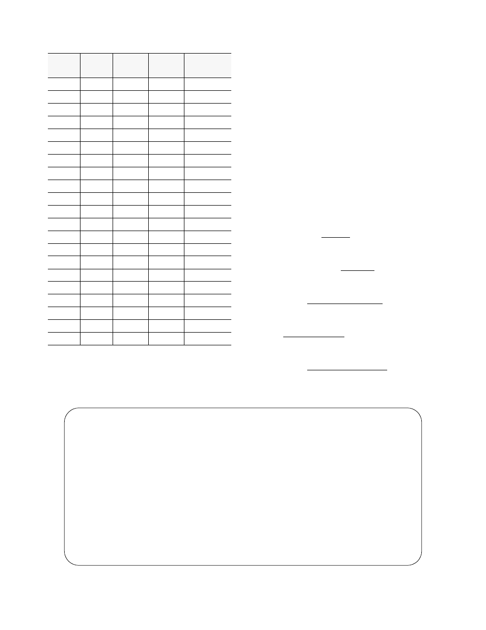
Trap Definitions
Cleared
Near
Cleared
Far
Alarmed
Near
Alarmed
Far
Description
4
54
104
154
DTE CRCES
5
55
105
155
DTE BPVS
6
56
106
156
DTE AISS
7
57
107
157
DTE RAS
8
58
108
158
DTE UAS
9
59
109
159
DTE OOFS
10
60
110
160
DTE LOSS
11
61
111
161
DTE CSS
12
62
112
162
DTE SES
13
63
113
163
DTE ES
14
64
114
164
NET CRCES
15
65
115
165
NET BPVS
16
66
116
166
NET AISS
17
67
117
167
NET RAS
18
68
118
168
NET UAS
19
69
119
169
NET OOFS
20
70
120
170
NET LOSS
21
71
121
171
NET CSS
22
72
122
172
NET SES
23
73
123
173
NET ES
24
74
124
174
Device Reset