Section 3.4, 4 t1 dte configuration – Verilink PRISM 3000 (34-00184) Product Manual User Manual
Page 20
PRISM 3000
3-4
Operation
the ‘
Timing
’ menu. The choices are ‘
N x 56 K
’, ‘
N x64 K
’,
and ‘
1.544
MHz
’.
Station Timing: This field selects the ‘N’ multiple when
‘
Station
Input
Timing
’ is set to either ‘
N x 56K
’ or
‘
Nx 64K
’ and only appears when ‘
Station
’ has been
selected from the ‘
Timing
’ menu. The ‘N’ range is 1 to 24.
For example, if N = 2 and ‘
Station
Input
Timing
’ is
set to ‘
N x 64K
’, the unit expects a 128 kHz clock on the sta-
tion input port (2 x 64 = 128).
PRM Enable: This field will ‘
ENABLE
’ or ‘
DISABLE
’ the
ANSI T1.403 Performance Report Message functions.
Zero Suppression: This field determines whether ones
density insertion is activated after 15 zeros. To ensure com-
pliance with TR54016, this field must be enabled. The
choices are ‘
ENABLE
’ and ‘
DISABLE
’.
Alarm Thresholds: The PRISM can be programmed to
generate an alarm condition based on a specific level of per-
formance degradation. Acceptable alarm thresholds are set
for periods of 15 minutes (900 seconds). The error types
listed below can be preset to a value between ‘
0
’ and ‘
900
’
seconds. A field set to ‘
0
’ causes the unit not to alarm on
that statistic. To effectively disable alarm reporting, set all
fields to ‘
0
’.
The 15-minute time frame is not based on the TR54016 or
T1.403 interval boundaries, but is a time window based on
the accumulated counts over the previous 15 one-minute
intervals. In all cases, if the number of actual network
errored seconds in the previous 15 minutes reaches the pre-
set threshold for the specified error type, an alarm condition
is declared.
Alarm Reset Timer: Sets the length of time after the alarm
condition clears before the alarm indication is removed. A
value of zero in this field will not allow the alarm to be
automatically cleared. The default value is 30 seconds.
ES: Sets the errored seconds threshold. The default value
is 45 seconds.
SES: Sets the severely errored seconds threshold. The
default value is 5 seconds.
LOSS: Sets the loss of signal seconds threshold. The
default value is 5 seconds.
OOFS: Sets the out of frame seconds threshold. The
default value is 5 seconds.
UAS: Sets the unavailable seconds threshold. The default
is 0 (disabled).
RAS: Sets the remote alarm seconds threshold. The
default is 0 (disabled).
AISS: Sets the alarm indication signal seconds threshold.
The default is 0 (disabled).
BPVS: Sets the bipolar violation errored seconds thresh-
old. The default is 0 (disabled).
3.4
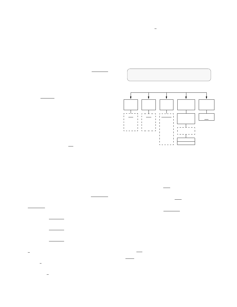
T1 DTE Configuration
The T1 DTE Configuration display allows configuration
parameters to be set the for the T1 DTE port (if equipped).
T1 DTE Configuration Screen & Diagram
Framing Type: Selects the type of framing for the T1 DTE
side of the unit. The PRISM permits framing conversion
from the DTE to the Network and from the Network to the
DTE (D4 to ESF and ESF to D4). Older D4 equipment can
be supported with newer ESF spans. Using ESF framing
allows the user and the telco access to the increased service-
ability and information available through the FDL protocols.
The choices are ‘
D4
’ and ‘
ESF
’.
Line Code: Selects the type of line coding for the DTE
side of the unit. The choices are ‘
AMI
’ and ‘
B8ZS
’.
DSX Level: Specifies the DTE DSX1 interface output
level. The choices are:
‘
0-110ft
’
‘
111-220 ft
’
‘
221-330 ft
’
‘
331-440 ft
’
‘
441-550 ft
’
‘
551-660 ft
’
‘
>660 ft
’
Channel Assignment: This field selects which of the 24
network channels are to be passed through to the T1 DTE
port. Channels which have been assigned to a high speed
port are indicated and can only be changed through the
‘
DTE
Port
Configuration
’ menu. The default is all
channels idle. Choices for the unassigned channels are:
IDLE: Sets the specified channel to transmit idle code on
the T1 DTE port and ignore received data.
THRU: Sets the specified channel to pass data from the
T1 DTE port to the network and vice versa.
T1 DTE Configuration
Framing Type ........
ESF
<
Framing
Type
Line
Code
DSX
Level
Channel
Assignment
ESF
D4
AMI
B8ZS
0 - 110 ft
111 - 220 ft
221 - 330 ft
331 - 440 ft
441 - 550 ft
551 - 660 ft
> 660 ft
Channels
1 - 24
Idle
Thru
Rem Com
Ports 1 - 4
Alarm
Threshold
DTE OOFS
000