Installation, Unpacking and inspection -1, Supplied materials -1 – Verilink PRISM 3101 (34-00212) Product Manual User Manual
Page 11: Rack mounting -1, Rack mount installation -1, Unpacking and inspection, Supplied materials, Rack mounting
Installation 2-1
PRISM 3101/3102
2. Installation
This chapter contains instructions for physically installing
the TxPORT PRISM 3101/3102 as either a standalone or
rack mount unit as well as information concerning the com-
munication ports and power supply on the rear of the unit.
Unpacking and Inspection
Upon receipt of your shipment, inspect the shipping con-
tainer and contents. If the contents of the shipment are
incomplete or, if there is mechanical damage or defect,
notify TxPORT Customer Service. If the shipping container
or cushioning material is damaged, notify the carrier and
TxPORT immediately and make a notation on the delivery
receipt that the container was damaged (if possible, obtain
the signature and name of the person making delivery).
Retain the packaging material until the contents of the ship-
ment have been checked for completeness and the instru-
ment has been checked both mechanically and electrically.
Supplied Materials
Your baseline PRISM 3101/3102 shipment contains three
items.
• PRISM 3101/3102 unit with a captive power supply
• T1 network cable (P/N 9-1544-619-009)
• Reference manual with configuration guides
For specific applications, you may require additional cables
and adapters. Ordering information is located on page 1-4.
Contact TxPORT Customer Service for further assistance.
Rack Mounting
The PRISM 3101/3102 is housed in a plastic case intended
for desktop installation. Kits are available which allow the
unit to be mounted into standard 19-inch (33.02 cm) or 23-
inch (58.42 cm) racks. This assembly occupies two rack
spaces at 3.5 inches (8.89 cm).
Supplied Materials
The 3101/3102 rack mount assembly consists of the follow-
ing items. Refer to the section Ordering Information on
page 1 -4 for ordering numbers.
• A casing supporting the bottom, sides, and rear of the unit.
• 19-inch or 23-inch plate that bolts to rack.
• Set of four bolts and nuts that attach the casing to the plate.
• Four screws that attach the assembly to the 19-inch or 23-
inch rack.
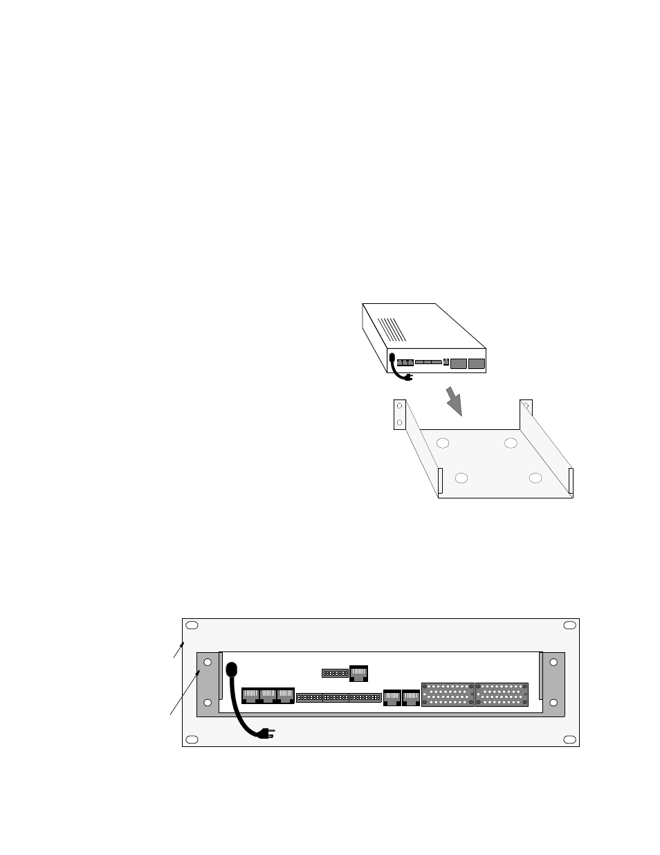
Rack Mount Installation
1. Insert the PRISM 3101/3102 (rear first) into the casing
as shown in Figure 2-1.
2. Connect this assembly to the 19-inch or 23-inch plate
using the four nuts and bolts as shown in Figure 2-2.
When the mounting plate is attached to the PRISM 3101/
3102 and the casing, the unit is secure and cannot be
pulled out of the assembly from the front.
Figure 2-1 Rack Mount Installation
Four (4) bolts attach
bracket to rack mount plate
SUPV
SLIP
LAN
NET
DATA PORT 2 DATA PORT 1
115 VAC
S1
S2
S3
Rack mount plate
Figure 2 -2 Rack Mount Assembly (Rear View)
DBU
T1
DTE
S4
60 HZ