Port connections -2, Lan -2, Port connections – Verilink PRISM 3101 (34-00212) Product Manual User Manual
Page 12: Prism 3100 series
Installation 2-2
PRISM 3101/3102
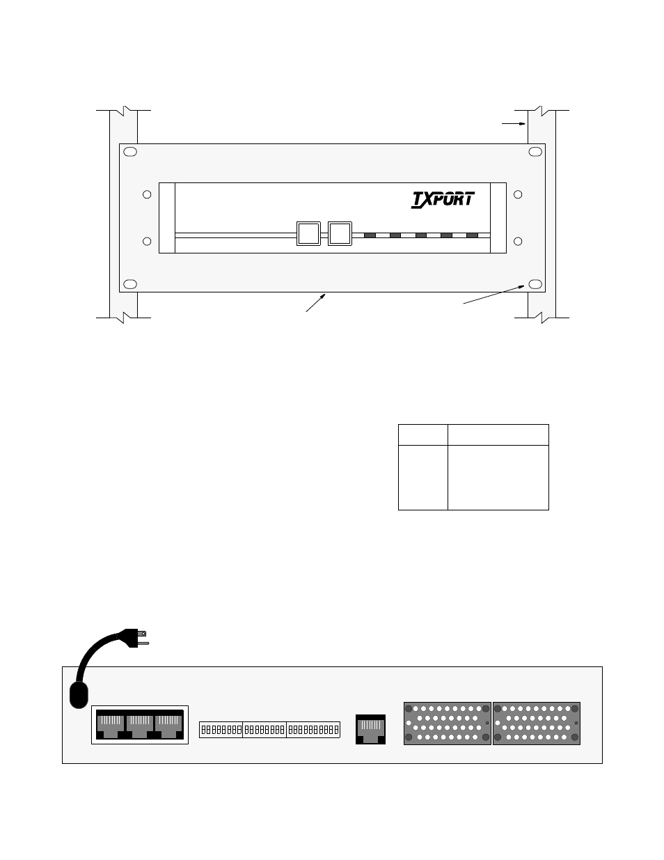
3. To install the rack mount assembly into a rack, tighten
the four sets of nuts and bolts that attach the plate to the
rack as shown in Figure 2-3.
Port Connections
On the rear of the PRISM 3101/3102, there are several port
connections as shown in Figure 2 -4: LAN, SLIP, SUPV, T1
DTE, NET, DBU, Data Port 1, and Data Port 2.
LAN
The PRISM 3101/3102 can be equipped with either an inter-
nal Ethernet or Token Ring network interface card (NIC) for
connection to a local area network (LAN). This port does
not function unless the optional NIC is installed. The
Ethernet interface is 10BASE-T. The Token Ring interface
is Type 3. The connection is an 8-pin modular jack on the
rear of the unit labeled LAN. This allows the NIC to be
installed without changing the rear panel.
The Simple Network Management Protocol (SNMP) agent
can then be programmed to take advantage of the central-
ized status monitoring and alarm reporting capability of
SNMP managed networks.
Ethernet: The Ethernet interface complies with standard
twisted pair, 10BASE-T requirements. Table 2-A displays the
pinout assignments for the 8-pin modular LAN connection.
Configure the LAN interface before connecting the PRISM
3101/3102 to the LAN network. See the section
SNMP Configuration on page 3-15 for specific information.
Token Ring: The Token Ring interface is designed to oper-
ate on both 4 and 16 Mbps networks and complies with
standard unshielded twisted pair (UTP) requirements. Table
ALARM
TEST
BACKUP
NET
TEST
LOOP
POWER
T
R
A
N
S
P
O
R
T
®
PRISM 3100 Series
Four (4) nuts and bolts
attach rack mount kit to rack
19" or 23" width available
Rack
Figure 2-3 Rack Mount Assembly (Front View)
SUPV
SLIP
LAN
NET
DATA PORT 2
DATA PORT 1
115 VAC
60 HZ
S1
S2
S3
8
1
1
8 1
10
Figure 2-4 PRISM 3101/3102 Rear Panel (dual port 3102 shown)
Table 2-A Ethernet Pinout Assignments
Pin
Ethernet Interface
1
Data Out (+)
2
Data Out (-)
3
Data In (+)
6
Data In (-)