Verilink PRISM 3101 (34-00212) Product Manual User Manual
Page 28
Configuration 3-12
PRISM 3101/3102
P
ORT
C
ONFIGURATION
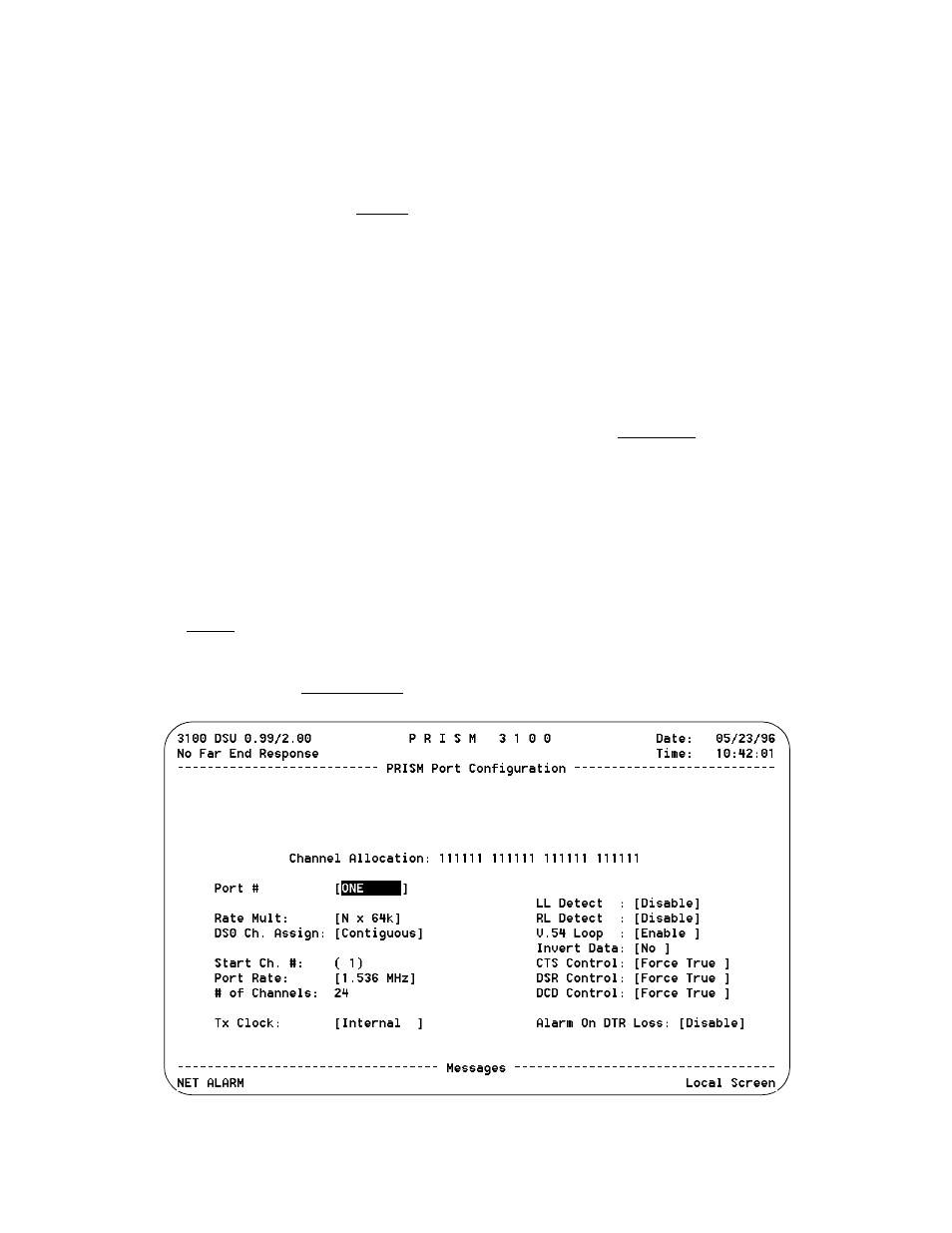
The Port Configuration screen (Figure 3-13) sets the operat-
ing parameters for each high speed port. The unit does not
allow conflicting configurations for the DTE ports. There-
fore, the selections for each menu item are restricted to
those that do not conflict with the configuration of the other
high speed port. The default is all channels disabled.
When channel assignment changes are made to the high
speed ports or to the remote communication link, the 3101/
3102 reestablishes the mapping of all channels. This inter-
ruption to traffic will normally result in a brief burst of data
errors on other ports.
Channel Allocation: This display-only field indicates the
network channel assignments with Channel 1 on the left and
Channel 24 on the right. Channels assigned to a port are
identified with a port number (1 or 2). Non-assigned idle
channels are marked with a dash ( -). Remote communica-
tion channels are marked with an ‘ R’. When channels are
assigned to a port in the ALTERNATE assignment mode,
each data channel is followed by an idle channel that is not
assignable for other ports and is marked with an X. T1-DTE
channels are shown with a D.
Port #: Selects the port to be configured, such as [ONE] or
[TWO].
Rate Multiplier: The unit can operate at any data rate that
is a multiple of 56 or 64 kbps. When Nx64K is selected, the
ones density requirements of the T1 network line must be
ensured. When Nx 56K is selected, the unit maintains ones
density for the selected DS0 channel.
DS0 Channel Assignment: Selects whether the DTE chan-
nel assignment will be made as a CONTIGUOUS group or
as ALTERNATE channels. Selecting ALTERNATE will
assure ones density but reduce the available bandwidth from
1.536 kbps to 768 kbps.
Start Channel #: The starting channel in the 24-channel
DS1 bit stream must be selected in this field. The unit then
assigns the following channels automatically according to
the bit rate multiplier and the mode selected in DS0 Channel
Assignment. The choices are 1 through 24.
Port Rate: Pressing the <spacebar> increases the required
port bit rate in increments of 56 or 64 kbps, depending on
the Rate Multiplier setting. The N multiplier ranges in value
from 0 to 24.
# of Channels: This field displays the number of channels
to be passed through to the DTE. The number is determined
by the Port Rate value divided by the Rate Multiplier.
Transmit Clock: This field is used to select the clock that
the unit will use to sample the data transmitted from the
DTE. When set to INTERNAL, the data is automatically
edge-aligned and sampled directly with the transmit data
clock that is also supplied to the DTE as Transmit Clock.
The EXTERNAL option uses the external clock supplied by
DTE. The OVERSAMPLE option is used to operate the port
as a low speed asynchronous port. In this mode, the port rate
should be set to at least 4 times the asynchronous data rate
(depending on the degree of allowable distortion for the par-
ticular DTE equipment used).
LL (Local Loop) Detect: Allows you to enable or disable
pin J (V.35) or pin 18 (EIA 530) to loop-up the near (local)
unit.
Figure 3-13 Port Configuration Screen