A. terminal interface, A, terminal interface, Screen components – Verilink PRISM 3101 (34-00212) Product Manual User Manual
Page 37: Cursor controls
Treminal Interface A-1
PRISM 3101/3102
A. Terminal Interface
This chapter describes the screens structure and menu con-
trols for the TxPORT PRISM 3101/3102 terminal interface.
The interface is a firmware application program embedded
inside the unit.
It requires an ANSI compatible VT100 terminal (ASCII), or
a computer running an ANSI terminal emulation program.
The terminal interface uses ASCII BREAK and ESCAPE
functions, which are implemented differently with the vari-
ous terminal emulation programs.
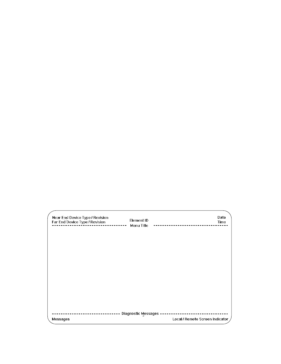
Screen Components
Terminal interface screens have several components com-
mon to all screens (Figure A-1).
Device Type and Revision: The device type (such as
PRISM 3102) and the revision control numbers are shown
in the upper left corner. The first number is the hardware
revision and the second number is the software revision.
Information is displayed for the near end unit (connected
directly to the terminal) on the top line, and for the far end
unit (connected to the network T1 interface) on the second
line. Refer to this information when contacting the factory
with inquiries.
The far end information is available only for TxPORT prod-
ucts that support a proprietary message set. If the far end
does not support these messages but does support the stan-
dard 54016 protocol, then the far end information is dis-
played as GENERIC 54016 FAR END. If the far end does
not respond to either proprietary or 54016 messages, then
NO FAR END RESPONSE will be displayed. If the far end
echoes the FDL messages transmitted by the near end unit,
then FAR END LINE LOOP is displayed.
Date/Time: The top right corner of the terminal screen dis-
plays the current date and time. The setting of these functions
is described in the section entitled Utilities on page 3-17.
Element ID: Below the header (PRISM 3100), the Element
ID is displayed. Refer to the section entitled
Management Ports on page 3-16 for information on the
Element ID.
Menu Title: The menu title (third line, center) denotes the
general classification of functions currently accessible by
the user (such as MAIN or PERFORMANCE).
Messages: Diagnostic messages may be displayed at the
bottom of the screen.
Local / Remote Screen Indicator: Identifies the visible
screen as displaying the local or remote interface.
Cursor Controls
The terminal interface utilizes a highlighted cursor to make
selections from menus and select fields within screens to be
operated on. The cursor is moved in different ways, depend-
ing on the terminal emulation program used. Most programs
allow use of the <tab> and <shift -tab> keys. Others allow
use of the arrow keys. Once a field is highlighted, it is
manipulated as described in Section .
Figure A-1 Terminal Interface Layout