Verilink PRISM 3101 (34-00212) Product Manual User Manual
Page 31
Configuration 3-15
PRISM 3101/3102
SNMP C
ONFIGURATION
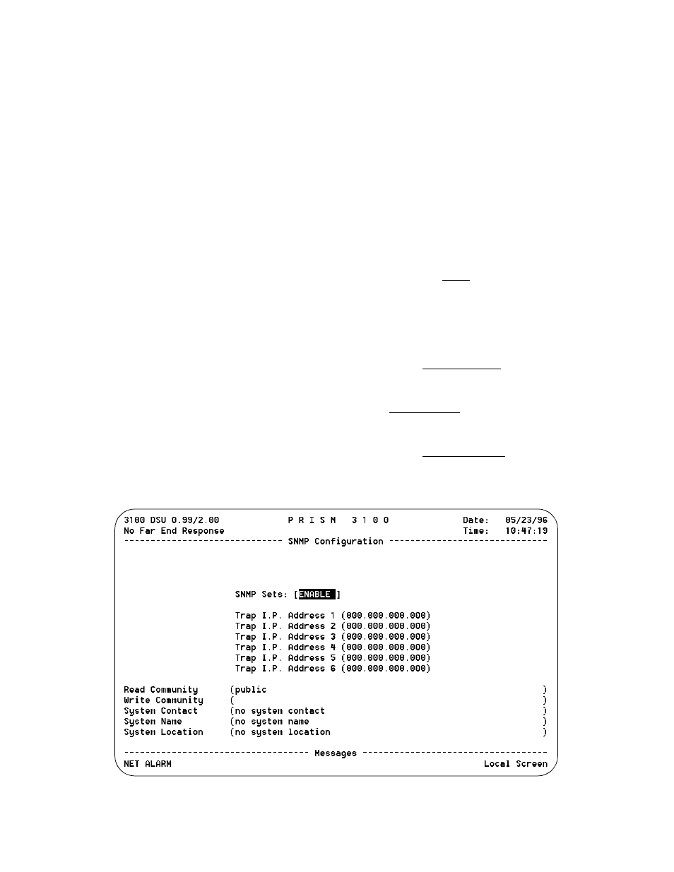
The SNMP Configuration screen (Figure 3-16) is accessible
for the SLIP, Ethernet or Token Ring SNMP interface. It
allows for the entry of those parameters required for proper
operation with an SNMP-based network manager.
The 3101/3102 supports alarm reporting by SNMP TRAPs
when running the LAN or SLIP interface. If the unit’s IP
Connection is LAN or Direct SLIP, it expects an IP connec-
tion to always be present and thus outputs its TRAP mes-
sages immediately. If the IP Connection is Dial SLIP, the
unit dials out from the modem connected to the SLIP port
using the number programmed in the SNMP Configuration
screen an outputs TRAP messages upon connection.
The PRISM 3101/3102 has an embedded SNMP agent sup-
porting MIB-2 and the DS1/E1 MIB. The SET command is
supported and has the functionality described below. The
3101/3102 also supports a single TELNET session.
SNMP Sets: This field enables or disables the set com-
mand responses for SNMP. Refer to Appendix C,
SNMP Agent for detailed information on these responses.
TRAP IP Address: These six rows require numeric
entries. Each row contains four 3-digit numbers which are
separated by periods. Each of these numbers can range from
0 to 255.
These fields accept the IP address of a network device to
which alarm reporting TRAPs are to be sent. The unit
detects and reports alarms and provides several options for
reporting them, one of which is SNMP TRAPs. When an
alarm occurs, the unit sends a trap message to up to 6 desti-
nations on the user’s network. The trap message is formatted
per RFC 1157. The generic trap type is enterpriseSpecific
(generic-trap = 6).
Up to 6 Trap IP addresses can be assigned to report via
SNMP. The unit will report each alarm by transmitting an
SNMP Trap to each Trap IP address. T1 network problems
often cause more than one alarm type. In these cases, multi-
ple trap messages are generated, each with a different spe-
cific trap type. The specific-trap field of each trap message
is set to one of the values shown in the Trap Definition table
on the previous page.
The following five menu items allow the entry of up to 58
characters identifying the appropriate group, person, device
function, or unit location.
Read Community: This display accepts a character string
identifying the group authorized to perform read operations.
The default setting is public.
Write Community: This display accepts a character string
identifying the group authorized to perform write opera-
tions. The default setting is a null string (‘ ‘).
System Contact: This display accepts a character string
identifying the person responsible for a network device. The
default setting is no system contact.
System Name: This display accepts a character string iden-
tifying the functionality of the network device. The default
setting is no system name.
System Location: This display accepts a character string
identifying the physical location of network device. The
default setting is no system location.
Figure 3 -16 SNMP Configuration Screen