Verilink PRISM 3101 (34-00212) Product Manual User Manual
Page 29
Configuration 3-13
PRISM 3101/3102
RL (Remote Loop) Detect: Allows you to enable or dis-
able the monitoring of pin BB (V.35) or pin 21 (EIA 530) to
loop-up the far unit.
V.54 Loop: Selecting Enable allows the unit to respond to
inband V.54 loop commands. If you select Disable, the unit
ignores these commands.
Invert Data: In the invert mode (YES), transmit and
receive data are inverted at the port interface. This function
may be used as a means of guaranteeing ones density when
the data is composed of SDLC type protocols. The choices
are YEs and NO.
CTS /DSR/DCD Control: Setting any of these three fields
to FORCE TRUE or FORCE FALSE allows the forcing of
the port control lead output state. INTERNAL allows for
normal operation.
Alarm on DTR Loss: Selecting [Enable] allows the unit to
go into alarm on loss of DTR. The default setting is [Dis-
able].
D
IAL
B
ACKUP
P
ARAMETERS
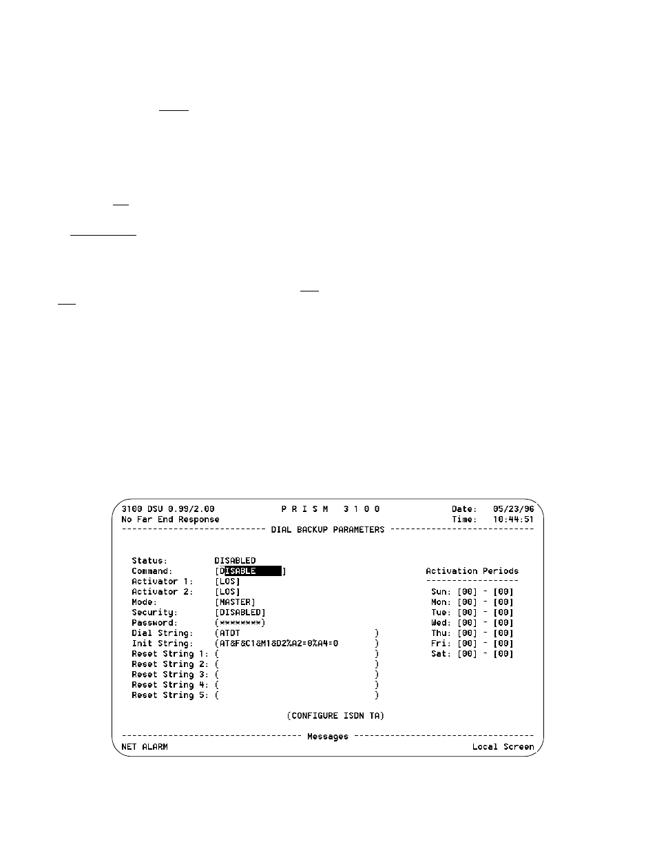
The Dial Backup Parameters screen (Figure 3-14) allows
you to configure the DBU port. You can enable the DBU
functionality by selecting two of the eight available alarm
indicators or by selecting ANY. These parameters can be
any one of nine errors (LOS, ES, SES, UAS, LOF, RAS,
AIS, BPV, ANY). These parameters allow you to establish
pre-defined thresholds (set in the Alarm Parameters screen)
and initiate dial backup when these thresholds are exceeded.
See Alarm Configuration on page 3-11 to set
the threshold parameters.
Alarm Reset Timer: This field can be set for zero to 900
seconds. If you set this field to zero, when you enter into
dial backup you will stay in that mode even if the T-1 circuit
is re-established. If you set this field from 1-900, the circuit
will be up that period before it re-establishes.
See Alarm Configuration on page 3-11 to set
the thresholds for this field.
Status: Lists the current DBU status as either Disabled,
Enabled, Active, Locked, Connecting, Disallowed, Dialing,
or Disconnecting.
Command: Disable, Enable, Enable Daily, Activate, or
Lock.
Activator 1: Allows you to set the first threshold value for
initiating a dial backup. Available values are LOS, ES, SES,
UAS, LOF, RAS, AIS, BPV, ANY.
Activator 2: Allows you to set the second threshold value
for initiating a dial backup. Available values are LOS, ES,
SES, UAS, LOF, RAS, AIS, BPV, ANY.
Mode: One unit must be configured as a master unit and
one unit must be configured as a slave. This determines pri-
orities when both units try to establish a DBU connection.
Security: Allows you to enable or disable the security
function limiting access to the DBU interface. The security
setting must be the same on both ends.
Password: If the security feature is enabled, the password
for the security option must be the same on both devices.
Dial String: Character string used to dial the other unit.
Init String:Character string used to configure the modem to
dial the other unit.
Figure 3-14 Dial Backup Parameters Screen