Line parameters -10 – Verilink PRISM 3101 (34-00212) Product Manual User Manual
Page 26
Configuration 3-10
PRISM 3101/3102
Line Parameters
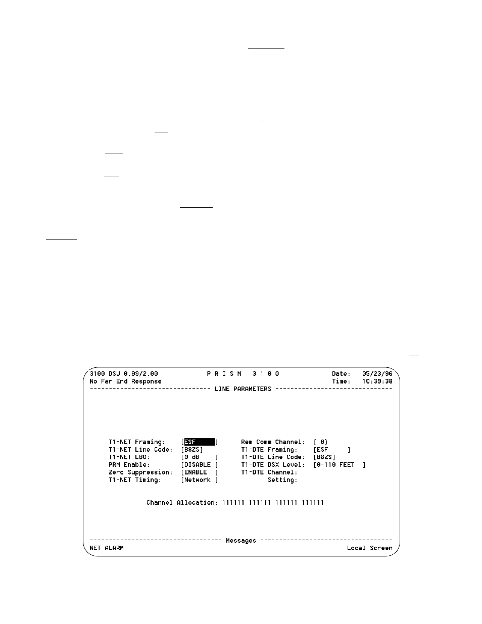
The Line Parameters screen (Figure 3-11) allows you to
review and set line parameters for the selected element on
the T1 circuit. This screen has the following fields, most of
which have user selectable options. To send the new line
configuration to the unit, either press <return> on one of the
fields, change the Element selection, or exit the screen.
T1-NET Framing: Selects the type of framing for the net-
work side of the element as either [ESF] and [D4].
T1-NET Line Code: Sets the network side line coding as
either [AMI] and [B8ZS].
T1-NET LBO: Sets the line build out for the network
interface as either [0 dB], [-7.5 dB], [-15 dB], or [-22.5 dB].
PRM Enable: This field allows the T1.403 Performance
Report Message, which is sent once a second, to be turned
on or off. The choices are [ENABLE] and [DISABLE].
Zero Suppression: This field determines whether ones
density insertion is activated after 15 zeros. The choices are
[ENABLE] and [DISABLE].
T1-NET Timing: Sets the timing source to synchronize
the unit’s internal timing generators. Slips are controlled to
occur on frame boundaries at the network and/ or DSX1
ports when timing synchronization is lost.
INTERNAL: The unit’s internal frequency standard is used
for all timing.
PORT 1: Timing is synchronized to the external terminal
timing clock supplied from the DTE and connected to the
selected port.
Verify that the external DTE clock is operating at
the data rate selected for Port 1.
NETWORK: Timing is derived from the network recovered
clock (most applications use this selection).
T1-DTE:The unit synchronizes the clock recovered from the
DSX-1 T1 DTE port.
Remote Comm Channel: This field selects a communica-
tion link to the far end unit. You can either assign a DS0
channel (1 through 24) or use an ESF facility data link (0).
If ‘0’ is selected, communication is established over the
ESF facility data link (valid only when the network inter-
face is configured for ESF and the FDL has end-to-end
integrity). For example, the entire T1 bandwidth must be
available to the user with no intervening multiplexors in the
signal path blocking the FDL.
As an alternative, the communication link may be assigned
to an unused idle channel. This option may be used whether
the network is operating in D4 or ESF modes.
When the remote communication is programmed to operate
over a spare network channel, test conditions such as a
remote network LLB or PLB or a local network LLB will
interrupt access to the far end unit.
When the remote communication is programmed to operate
over the facility data link (FDL), test conditions such as a
remote network LLB or a local LLB on the near end will
interrupt access to the far end unit.
If far end communication is interrupted for any
reason while accessing the remote unit, you
should exit and then reenter this screen to ensure
that all the parameters have been updated.
T1-DTE Framing: Selects the type of framing for the T1-
DTE side of the element. The unit will support ESF to SF
or SF to ESF conversions. The choices are ESF or D4.
Figure 3-11 Line Parameters Screen