Switch s2 -2, Switch s3 -2, Switch s2 – Verilink PRISM 3101 (34-00212) Product Manual User Manual
Page 18: Switch s3
Configuration 3-2
PRISM 3101/3102
ones density requirements of the T1 network line must be
ensured in this mode. Refer to the section entitled
Line Parameters on page 3-10 for more information.
Selecting Nx56K (Up) allows port bit rates that are multi-
ples of 56 kbps. The unit maintains ones density for the
selected DS0 channel in this mode.
Data Port 2: Switch S1-8 sets the multiplier for Data Port
2 on the 3102 only. The unit can operate at any data rate that
is a multiple of 56 or 64 kbps. Selecting Nx64K (Dn) pro-
vides port bit rates that are multiples of 64 kbps. The ones
density requirements of the T1 network line must be
ensured in this mode. Refer to the section entitled
Line Parameters on page 3-10 for more information.
Selecting Nx56K (Up) allows port bit rates that are multi-
ples of 56 kbps. The unit maintains ones density for the
selected DS0 channel in this mode.
Switch S2
Switch S2 (Figure 3-3) configures parameters for Network
Framing, Network Coding, Network LBO, Timing Source,
Test Button loop Code, and Test Button Mode.
Network Framing: Switch S2-1 matches the unit to the
network line framing as either ESF (Dn) or D4 (Up).
Network Coding: Switch S2-2 sets the network line cod-
ing to either B8ZS (Dn) or AMI (Up).
Network LBO: Switch S2-3 and S2-4 set the line build
out signal level of the transmit data (TXD) from the unit to
the network. The telephone company can provide the
proper setting.
If unsure of the exact setting, leave it at the
default value. Table 3-C lists the available levels.
Timing Source: Switch S2 -5 and S2-6 determine the unit
clocking source. The most common timing source for CSU/
DSU applications is the network. The 3101/3102 may also
be optioned to time from an internal standard or from the
high speed data interface as shown in Table 3-D.
Test Button Loop Code: Switch S2-7 selects either an
inband line loopback code (Dn) or an inband V.54 loop code
(Up) for use with the front panel test button. On the 3102
model, this switch applies to Data Port 1 only.
Test Button Mode: Switch S2 -8 selects the test button
operation mode as either BERT (Dn) or Clear (Up).
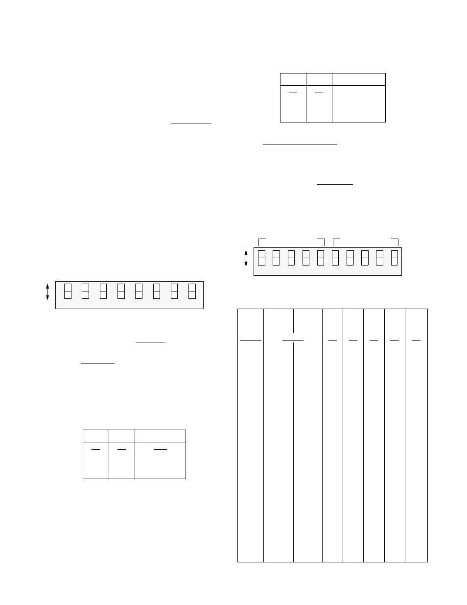
Switch S3
Switch S3 (Figure 3-4) sets the Port 1 and Port 2 bit rates as
shown in Table 3-E. Positions S3-6 through S3 -10 are not
applicable on the 3101.
Table 3-C Network LBO
S2-3
S2-4
Network LBO
Dn
Dn
0 dB
Up
Dn
-7.5 dB
Dn
Up
-15.0 dB
Up
Up
-22.5 dB
7
6
5
4
3
2
1
Dn
Up
8
Netwo
rk
Netwo
rk
Netwo
rk
T
est Butto
n
T
est Butto
n
Fra
m
in
g
Co
d
in
g
Mo
de
Lo
op
C
o
de
Ti
m
in
g
So
urc
e
LBO
Netwo
rk
LBO
Switch
S2
Ti
m
in
g
So
urc
e
Figure 3-3 Switch S2
Table 3-D Timing Source
S2-5 S2-6 Timing
Source
Dn
Dn
Network
Up
Dn
Internal
Dn
Up
Port 1 EXC
Up
Up
T1 DTE
Table 3-E Port 1/Port 2 Bit Rates
# of
DS0s
S1-7
Up S1-7
Dn S3-1 S3-2 S3-3 S3-4 S3-5
S1-8
Up S1-8
Dn S3-6 S3-7 S3-8 S3-9 S3-10
Disable
Disable
Dn Dn Dn Dn Dn
1 56
kbps
64
kbps Up Dn Dn Dn Dn
2
112
128
Dn
Up Dn Dn Dn
3
168
192
Up Up Dn Dn Dn
4
224
256
Dn
Dn Up Dn Dn
5
280
320
Up Dn Up Dn Dn
6
336
384
Dn
Up Up Dn Dn
7
392
448
Up Up Up Dn Dn
8
448
512
Dn
Dn Dn Up Dn
9
504
576
Up Dn Dn Up Dn
10
560
640
Dn
Up Dn Up Dn
11
616
704
Up Up Dn Up Dn
12
672
768
Dn
Dn Up Up Dn
13
728
832
Up Dn Up Up Dn
14
784
896
Dn
Up Up Up Dn
15
840
960
Up Up Up Up Dn
16
896
1024
Dn
Dn Dn Dn Up
17
952
1088
Up Dn Dn Dn Up
18
1008
1152
Dn
Up Dn Dn Up
19
1064
1216
Up Up Dn Dn Up
20
1120
1280
Dn
Dn Up Dn Up
21 1176
1344
Up Dn Up Dn Up
22
1232
1408
Dn
Up Up Dn Up
23
1288
1472
Up Up Up Dn Up
24
1344
1536
Dn
Dn Dn Up
Up
8
7
6
5
4
3
1
D
n
U
p
10
Switch
S3
2
9
Port 1 Bit Rate
Port 2 Bit Rate
Figure 3-4 Switch S3