Configuration, Hardware configuration -1, Switch s1 -1 – Verilink PRISM 3101 (34-00212) Product Manual User Manual
Page 17: Hardware configuration, Switch s1
Configuration 3-1
PRISM 3101/3102
3. Configuration
The PRISM 3101/3102 can be configured through manual
switch settings and/or through a VT100 terminal connection
to the supervisory port.
All default options in this manual are underlined.
Hardware Configuration
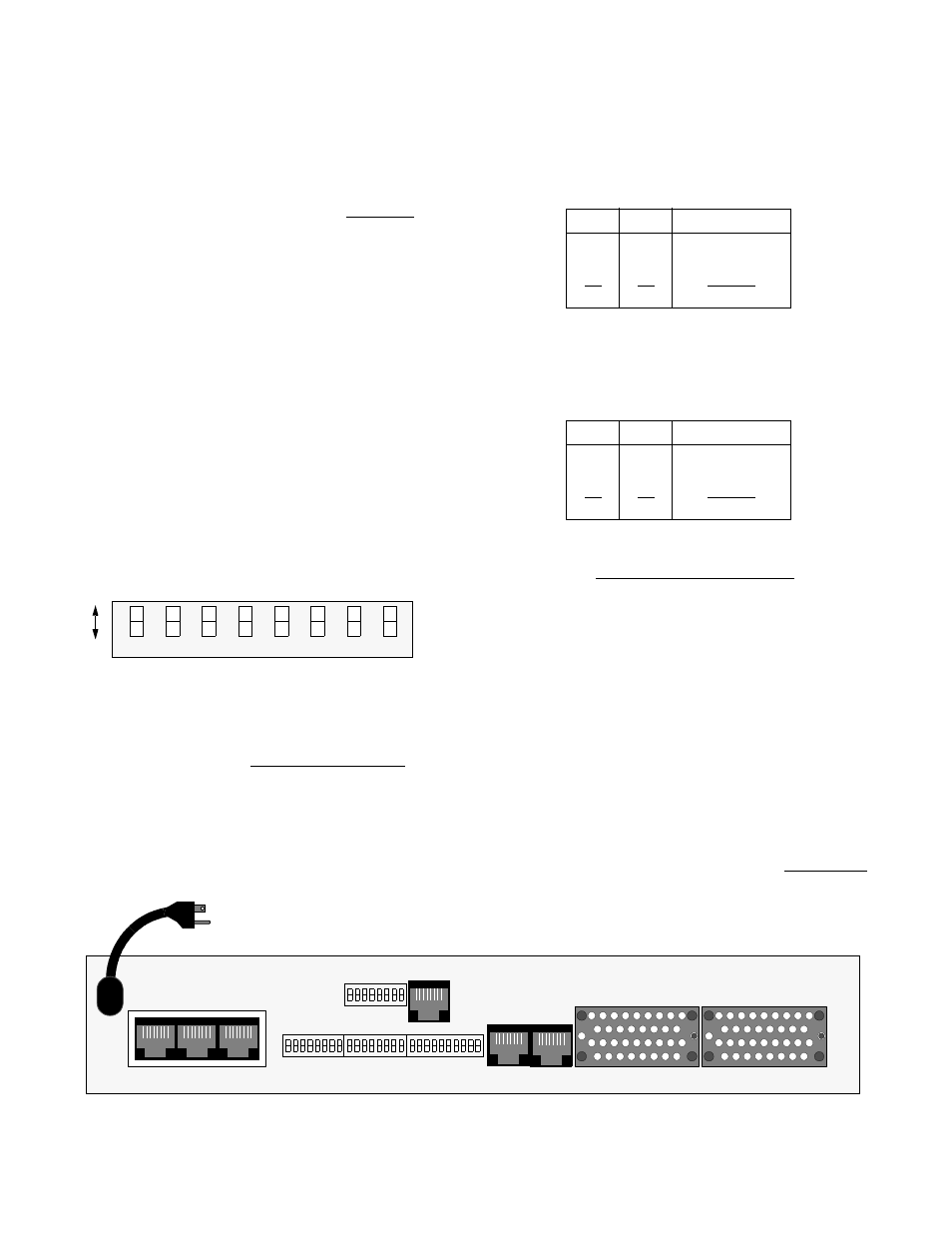
Hardware configuration is set using four dual in-line pack-
age (DIP) switches located on the rear of the unit. These
switches allow you to configure simple applications. Refer
to Figure 3 -1 for switch locations. A removable configura-
tion guide (45-00103) is included in the back of this manual.
Switch S1
Switch S1 (Figure 3 -2) configures the boot mode, SUPV
Port Bit Rate, SLIP Port Bit Rate, Channel Assignments,
Data Port 1, and Data Port 2. The SUPV and SLIP switches
(S1-2 through S1-5) cannot be modified through the termi-
nal interface.
Boot Mode: Switch S1-1 determines whether the unit con-
figures itself from the DIP switches or from the battery
backed RAM. If set to boot from RAM (Up), the switch set-
tings are ignored. If set to boot from switches (Dn), the unit
reads the DIP switches on power-up and configures accord-
ingly. Once running, configuration changes can be made
through the terminal interface, overriding the switch settings.
SUPV Port Bit Rate: Switch S1-2 and S1-3 set the
supervisory port bit rate. This is a serial RS-232 DCE port
configured for 8 bits, no parity, and 1 stop bit. Table 3-A
shows the available speeds.
SLIP Port Bit Rate: Switch S1-4 and S1-5 set the SLIP
port bit rate. This is a serial RS-232 DCE port configured
for 8 bits, no parity, and 1 stop bit. Table 3-B shows the
available speeds.
Channel Assignment: Switch S1-6 selects the channel
assignment mode for network T1 DS0s carrying data to the
high speed port. Contiguous channel mode (Dn) assigns the
channels as a block beginning at channel one for Data Port 1
and the first available channel for Data Port 2, if installed.
For example, if the high speed port data rate is to be 256
kbps (as defined by Switch S3), the unit assigns network
channels one through four to the high speed port.
Alternate (Up) channel mode assigns an idle channel follow-
ing each data channel. For example, data are carried on
channels 1, 3, 5, and 7. Channels 2, 4, 6, and 8 are idle (the
idle setting is binary code 01111111). The advantage of
alternate channel assignment is that T1 ones density require-
ments are maintained by the idle channels rather than plac-
ing any restrictions on the high speed data.
Data Port 1: Switch S1 -7 sets the multiplier for the Data
Port 1 input timing. The unit can operate at any data rate
that is a multiple of 56 or 64 kbps. Selecting Nx64K (Dn)
provides port bit rates that are multiples of 64 kbps. The
SUPV
SLIP
LAN
NET
DATA PORT 2
DATA PORT 1
115 VAC
60 HZ
S1
S2
S3
8
1
1
8 1
10
T1
DTE
S4
1
8
DBU
Figure 3 -1 PRISM 3101/3102 Rear Panel (dual port 3102 shown)
7
6
5
4
3
2
1
Dn
Up
8
Bo
o
t
SU
P
V
Po
rt
SU
P
V
Po
rt
Data P
o
rt
1
Data P
o
rt
2
Mo
de
Bi
t Rate
Ra
te
M
u
lt
ipl
ie
r
Ra
te
M
u
lt
ipl
ie
r
Ch
an
n
el
Assign
men
t
Bi
t Rate
S
L
IP Po
rt
Bi
t Rate
Switch
S1
S
L
IP Po
rt
Bi
t Rate
Figure 3-2 Switch S1
Table 3-A SUPV Port Bit Rate
S1-2
S1-3 SUPV
Port
Rate
Up
Up
1.2 kbps
Dn
Up
2.4 kbps
Dn
Dn
9.6 kbps
Up
Dn
19.2 kbps
Table 3-B SLIP Port Bit Rate
S1-4
S1-5 SLIP
Port
Rate
Up
Up
1.2 kbps
Dn
Up
2.4 kbps
Dn
Dn
9.6 kbps
Up
Dn
19.26 kbps