Verilink PRISM 3101 (34-00212) Product Manual User Manual
Page 32
Configuration 3-16
PRISM 3101/3102
M
ANAGEMENT
P
ORTS
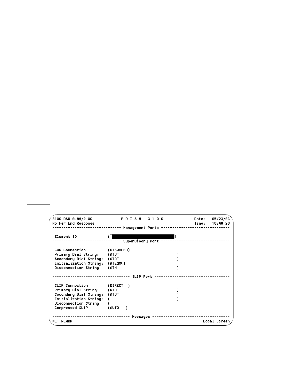
The Management Ports screen (Figure 3-17) sets the fol-
lowing parameters for the Call On Alarm (COA) connection
on both the SUPV and SLIP ports.
Element ID: This field allows the entry of an ASCII string
(29 characters in length) which identifies the unit to the
device receiving the alarm notification messages.
Call on alarm messages are reported in the following format
in the [DIAL] or [DIRECT] modes only:
Element ID HH:MM:SS MM/DD/YY <CR> <LF>
NET Alarms: alarms <CR> <LF>
DTE Alarms: alarms <CR> <LF>
where (alarms) is a string consisting of some or all of the
identifiers LOS, OOF, RAS, AIS, UAS, ERRS, or NONE.
The following is an example:
Joesunit 17:24:55 08/04/93
NET Alarms: LOS AIS ERRS
DTE Alarms: LOS Port1
The user programmable Element ID string is transmitted
first to allow the COA function to send a message with a
specific meaning to some host (such as a log on message).
The identifier
ERRS
represents an alarm that is
caused by ES, SES, and /or BPV errors.
COA Connection (SUPV): This field controls the remote
alarm reporting. ASCII alarm reporting through the supervi-
sory port is independent of TRAP alarm reporting. The
ASCII alarm report type is set by the following choices:
[DISABLED] - Alarm reporting is disabled.
[DIAL] - Sends reports through an attached AT command
set compatible modem connected to the SUPV serial port,
which must dial out to a remote modem. The message for-
mat is described in the Element ID field.
[DIRECT] - Sends reports to a printer or terminal connected
directly to the supervisory port.
Primary Dial String, Secondary Dial String: These fields
are ASCII strings for the primary and secondary call on
alarm phone numbers used in the [DIAL] mode. The strings
must NOT include the ATDT command prefix.
The unit attempts 3 times to connect using the primary num-
ber. If all 3 attempts fail, it will attempt 3 times to connect
using the secondary number (if it is not blank). If the sec-
ondary number fails, the unit waits 5 minutes and then
attempts to communicate with the primary number again.
When a connection is detected, the unit outputs the notifica-
tion message (as described in the Element ID field) and then
disconnects.
Initialization String: The modem initialization string is
entered in this field. Refer to the modem’s documentation
for further information. The default setting is
ATEQ0V1
.
Disconnect String: This field identifies the character string
to be output when the modem session is terminated. The
default setting is
ATH
.
COA Connection (SLIP): This field controls remote alarm
reporting. ASCII alarm reporting through the SLIP port is
independent of TRAP alarm reporting. The ASCII alarm
report type is set by the following choices:
[DISABLED] - Alarm reporting is disabled.
[DIAL] - Sends reports through a modem to the SLIP
server.
Figure 3-17 Management Ports Screen