Net -4, Dbu -4, Data port connections -4 – Verilink PRISM 3101 (34-00212) Product Manual User Manual
Page 14: Jack. table 2-c, Data port connections
Installation 2-4
PRISM 3101/3102
linecoding of the network interface. ESF to D4 conversion
is supported.
NET
The Network interface connection contains an automatic
line build out (ALBO) allowing the unit to be located a sub-
stantial distance away from the telco network interface with
a receive signal level down to -27 dB.
The network interface LBO level should be set as instructed
in the Line Parameters section on page 3-10. Maximum
suggested cable lengths for the connection from the unit to
the network are listed in Table 2-D. Calculations are based
on a cable temperature of 70
°
F, 0.083 uF /mile capacitance,
a 27 dB loss, and a 100
Ω
, non-loaded, twisted pair cable.
The network physical interface is a standard RJ-48C 8-pin
modular jack. Table 2-E displays the pinout assignments.
In accordance with FCC Rules, Part
68.218(b), you must notify the tele-
phone company prior to disconnecting
this product.
DBU
The Dial Back-Up (DBU) port provides an alternate path
when the T1 network interface service is disrupted or perfor-
mance quality is degraded. This port is a 10-pin RS-232 port
that can connect, through a connector adapter, to a public
switched digital network (PSDN) device such as a TxPORT
PS500. Table 2-F displays the pinout assignments. See page
3-13 for information on DBU parameters and settings.
Data Port Connections
The PRISM 3101 is equipped with either a V.35 port (on a
standard 34-pin connector) or with an EIA 530 port (on a
standard 25-pin DB-25 connector). The PRISM 3102 is avail-
able with either two V.35 ports or with two EIA 530 ports.
A standard EIA 530 to RS-449 conversion cable may be
used to adapt the DB-25 high speed port connection to 37-
pin RS-449 compatible data equipment. Pin functions for
both high speed port interfaces are listed in Table 2-G.
Default settings route all available DS0s to the T1 DTE port.
FCC rules require that interconnect-
ing cables carrying high speed data
be shielded appropriately in order to min-
imize radio frequency interference.
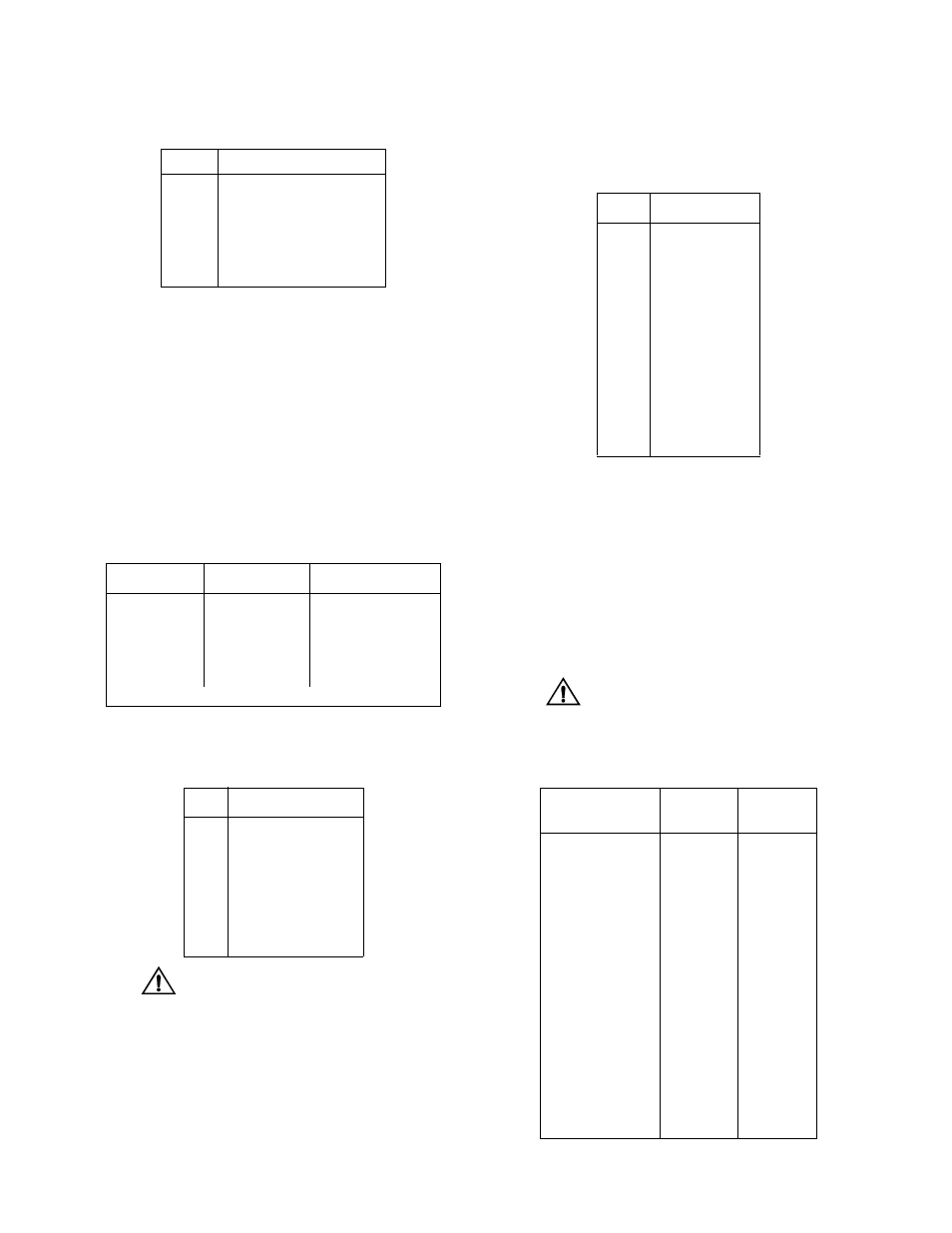
Table 2-C T1 DTE Pinout
Pin
T1 DTE Interface
1
Data Out
2
Data Out
3,6
Not Used
4
Data In
5
Data In
7,8
Chassis Ground
Table 2-D Maximum Cable Lengths
Cable Type
Loss per 1000'
Max Cable Length
26-gauge PIC
6.8 dB
4,400 ft
24-gauge PIC
5.4 dB
5,500 ft
22-gauge PIC
4.2 dB
7,100 ft
19-gauge PIC
3.0 dB
10,000 ft
PIC - Plastic Insulated Cable
Table 2-E Network Interface Pinout
Pin
T1 NET Interface
1
Data In
2
Data In
3, 6
Not used
4
Data Out
5
Data Out
7, 8
Chassis Ground
Table 2-F DBU Port Pinout
Pin
Connection
1
Rx Clock In
2
DTR Out
3
RTS Out
4
Frame Ground
5
Data Out
6
Data In
7
Signal Ground
8
CTS In
9
DCD In
10
Tx Clock In
Table 2-G High Speed DTE Interface
Common Name
EIA 530
DB-25
V.35
34-pin
Frame Ground
1
A
Transmit Data
2, 14
P, S
Receive Data
3, 16
R, T
Request to Send
4, 19
C
Clear to Send
5, 13
D
Data Set Ready
6, 22
E
Signal Ground
7
B
Data Carrier Detect
8, 10
F
Transmit Clock
15, 12
Y, AA
Receive Clock
17, 9
V, X
Local Loopback
18
J
Data Term Ready
20, 23
H
Remote Loopback
21
BB
Terminal Timing
24, 11
U, W